Let us look deeper into the rod/slot paradox of Special Relativity. We know already that one can set up very different scenarios of the rod/slot encounter in two dimensions. The easiest way to do so is to use different reference frames to define the initial conditions. We have already analyzed the perceptions of a variety of observers for two basic scenarios: a transit scenario (see the posts VIII to IX in this series) and a collision scenario (see the first six posts). We now want to directly compare data for these two scenarios in one and the same reference frame and, of course, at the same point in time, there.
In the preceding post we have already succeeded with a direct scenario comparison in a specific frame W. The origin of W approached the origin of a standard setup frame A for the collision scenario on a specific diagonal path (see the 8th post of this series). We could make the comparison after a Lorentz Transformation [LT] of the collision scenario’s data from frame A to frame W.
As expected, we saw major differences between specific quantities of the moving objects in our scenarios, namely regarding
- the angle between the rod and the slot and both their inclination angles vs. the line defined by the relative motion of the frames’ origins vs. each other,
- and the velocity vectors of the rod and the slot.
The differences were in part due to the impact of the Thomas-Wigner rotation.
In this post we prepare a direct comparison of the two scenarios in our standard setup frame A for the collision scenario. We perform a Lorentz Transformation [LT] of the transit scenario’s data from the diagonally moving frame W to A. If you are new to this series, a reading of previous posts may be required to understand the steps taken.
Previous posts:
- Post I: Special relativity and the rod/slot paradox – I – seeming contradictions between reference frames
- Post II: Special relativity and the rod/slot paradox – II – setup of a collision scenario
- Post III: Special relativity and the rod/slot paradox – III – Lorentz transformation causes inclination angles
- …
- Post VIII: Special relativity and the rod/slot paradox – VIII – setup of a transit scenario with the rod moving through the slot
- …
- Post XVI: Special relativity and the rod/slot paradox – XVI – perception of rod/slot collision in a diagonally moving frame
- Post XVII: Special relativity and the rod/slot paradox – XVII – conditions of the collision scenario as seen in a setup frame for the transit scenario
The transit scenario in the setup frame W
Let us call the slot and the rod of the collision scenario “c-slot” and “c-rod“, respectively. For the transit scenario we use the names “t-slot” and “t-rod“.
Just to remind you about the results of the preceding post:
The following schematic drawing shows on its left side a transit scenario for the “t-rod” and the “t-slot” in frame W at a time tW = 0. On the right side of the ys,W-axis a collision scenario unfolds between the “c-rod” and the”c-slot“.
Note: Both the c-slot and the t-slot have the same length and velocity in our frame W. This makes our comparison especially instructive.
The x-axis xs,W of the coordinate system for frame W was chosen such that the c-slot of the collision scenario resided on this axis. I.e., there was an alignment of the xs,W -axis with the c-slot’s orientation.
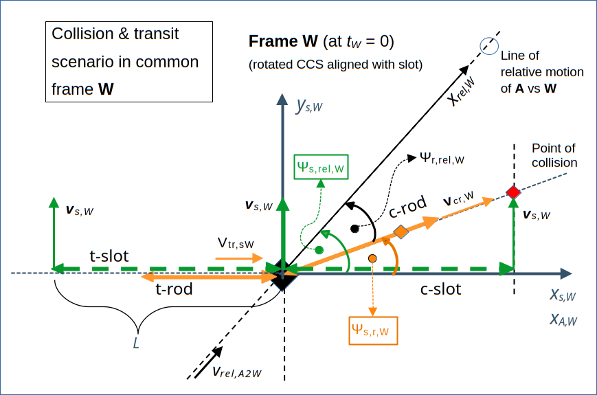
Illustration 1: Comparison of the transit scenario and the collision scenario in a common frame W at time tW = 0. At this moment the transit scenario (still) unfolds on the left side of the ys,W-axis, whereas the collision scenario takes place on the right side of the ys,W-axis. The conditions of the transit scenario are equivalent to the setup in a frame Z, which we used in previous posts. The length of the t-rod is measured to be shorter than its proper length (Ltr,W < L) due to the relativistic length contraction effect.
From the perspective of W the origin of frame A approaches W‘s origin on a diagonal path with a velocity vrel,A2W = vrel. See preceding posts for more details.
As in previous posts, we assume that there infinitesimally thin plates outside the c-slot and the t-slot. Note: The assumed impenetrable and infinitesimally thin plates around the slots are omitted in this and further drawings for the sake of clarity. We only show the slots themselves.
Remarks on the collision scenario:
The peculiar appearance of the collision scenario in W is due to the impact of the Thomas-Wigner rotation on rod and the slot. This rotation in turn is a result for the LT from frame A to the diagonally moving frame W. We have discussed details already extensively. The length Lcs,W of the c-slot as perceived in W was found to be Lcs,W = L. The reason lies in the vertical relative motion of W‘s origin vs. the c-slot in A.
Remarks on the collision scenario: The t-rod is just passed by the vertically moving ends of the t-slot at tW = 0 – admittedly at the last possible moment. So, no collision with surrounding plates, but just a transit of the t-rod through the t-slot. A reader has asked why the transit is set up in such an extreme way regarding the timing. This was just done to make the problem mathematically a bit more handsome. But, in your own calculations you may move the t-rod a bit to the left, without changing any of the qualitative results.
Basic quantities and relations
Let me remind you about some mathematical aspects of the properties indicated in illustration 1. We derived respective values in previous posts (see the 13th and 14th post of this series).
Both the perceived length Lcs,W of the c-slot and the set length Lts,W of the t-slot in W are equal to the proper length L of these objects:
We have introduced this length in the very first posts already.
The relativistic factors βx and βy refer to the (absolute) values νx and vy of the slot’s horizontal velocity and the rod’s vertical velocity, respectively, in our standard frame A. They also define the relative velocity vrel of the A/W-frames’ origins vs. each other:
The angle Ψs,rel,W between the c-slot and the line of relative motion between our frames A and W is given by
Below we will often use the absolute value of the sine. The direction of quantities is in most cases obvious.
The common vertical velocity vs,W of the c-slot and the t-slot in W‘s coordinate system with axes xs,W and ys,W has a positive value of :
Note that the vertical velocity vector vs,W and its absolute value vs,W are completely determined by the relative motion of the frame W vs. A.
Objectives of this post
We want to transform position and velocity data of the t-rod and t-slot from frame W to frame A. I present the the results below. The analysis of consequences is the topic of forthcoming posts.
The mathematics is a bit complicated and depends strongly on the choice of the t-rod/t-slot velocities. But the steps required to perform the LT follow familiar patterns which we have established already in other posts. Aside of some hints, I will not go into details. Once again, one has to take care of the correction of time points in W (and related spatial coordinates) to enforce a LT of spatially separated events to a common time tA = 0 in A.
I have discussed the special values chosen for vts,W and vtr,W in the preceding post, already:
and
Within the usual limit, we could at least in principle have chosen a different value for the horizontal velocity vtr,sW of the rod along the xs,W-axis. I will, therefore, present results for the t-rod’s coordinates and velocity components first in form of general formulas depending on vtr,sW (and respective factors βtr,sW and γtr,sW) and only afterward as derived for the specific value of vtr,sW given above.
Lorentz Transformation of the coordinates of the t-slot for tA = 0
If you want to apply the LT between W and A in its common simple form, you have to perform it in a (rotated) Cartesian coordinate system with an xrel,W -axis aligned with the line of the frames’ relative motion. The xrel,W-axis is thereby also aligned with the vector vrel,A2W, as perceived in W. x-coordinate-values in this coordinate system get a subscript “rel” below. W
The right end point of the t-slot poses no problem during the LT. Its trel, xrel and yrel -coordinates get a value of 0 both in W and A. However, an important requirement for a correct LT of the t-slot’s left end point is that you need to pick x– and y-coordinates at a time tW that transforms to tA = 0. We have gone through the necessary steps to achieve this already very often in this post series. I leave the straightforward operations to the reader. You must, of course, also perform projections of the position and velocity vectors onto the axes xrel,W and yrel,W to determine the required values.
I call the relevant time coordinate tts,l,rel,W (< 0) and the respective spatial coordinates xts,l,rel,W (along the xrel,W-axis) and yts,l,rel,W (along the perpendicular yrel,W -axis).
Expectations: Similar to the initial conditions set for the c-slot in frame A, we expect the length of the t-slotto become 1/γx * L in frame A . Its orientation there should also be along the xA-axis.
The corrected coordinates in W, which become subject to the LT (to tA = 0) , are:
with
The Lorentz Transformation (in its simple form along the line of relative motion) then gives us:
This in turn indeed gives us, with the uniquely defined vertical velocity vts,W and the values for the angle Ψs,rel,W, the following results
and
The respective angle just defines an orientation of the slot along the xA-axis. Together with the right end of the slot coinciding with the origin of A at tA = 0, this tells us the following:
In frame A the t-slot resides on the xA-axis – to the left of A‘s origin.
Lorentz Transformation of the velocity components of the t-slot for tA = 0
The velocity components vts,x,rel,W (along the xrel,W-axis) and vts,y,rel,W (along the yrel,W-axis) of the t-slot’s velocity are given by
They transform to respective constant components in A:
The negative signs results from the difference of the component vts,x,rel,W and vrel in the LT-formulas. As a consequence we find for the perceived velocity value vts,A of the t-slot in A and its angle Ψv,ts,rel,A with the xrel,A-axis:
Just, as we had expected:
In frame A, the t-slot moves to the left with the same velocity as the c-slot in the collision scenario.
Lorentz Transformation of the coordinates of the t-rod for tA = 0
The rod is a bit more difficult to handle. Its length in W is contracted in comparison to its proper length:
With this we get after a somewhat lengthy calculation the right coordinates ttr,l,rel,W , xtr,l,rel,W and ytr,l,rel,W, which we must use for the LT to A to get results for a point in time ttr,l,rel,A = 0 :
with
The factor 1/Ntr accounts for the required shift in time to fix a LT to ttr,l,rel,A = 0.
The formulas for the spatial coordinates have some symmetry as the left end of the rod resides on the xrel,W -axis also at ttr,l,rel,W .
After the LT we expect some impact of the Thomas-Wigner rotation. A lengthy calculation delivers respective data in frame A:
From the sign of xtr,l,rel,W we conclude that:
In frame A, the t-rod is located to the left of the yA-axis.
The length Ltr,A of the t-rod and its angle Ψtr,rel,A with the line of the frames’ relative motion in A are given by:
The angle between the t-rod and the xA-axis
A very interesting thing is: For our specific coupling of the scenarios, the angle Ψtr,rel,A does not depend on the velocity of the t-rod in W. The reason lies in the horizontal alignment of the t-rod with the xs,W-axis and resulting linear scaling of the components along the axes xrel,W, yrel,W.
The angle Ψs,rel,W is fixed (!) by the collision scenario and the relative movement of W vs. A. We use the results of previous posts (see above) for Ψs,rel,W to further analyze the angle Ψtr,rel,A:
It follows that
I.e., the angle between the t-rod and the line of relative motion between W and A is bigger in frame A than the respective angle of the c-slot or t-slot, there. As the slots reside on the xA-axis, the rod has an acute angle relative to the xA-axis and thus also relative the t-slot in A. Meaning:
The left end of the t-rod resides at tA = 0 above the xA-axis (left to the origin), while the right end coincides with A‘s origin.
See illustration 2 in a section below. This is, of course, due to the impact of the Thomas-Wigner rotation on the t-rod.
The length of the t-rod in A for our special selection of the t-rod’s velocity
The length of the t-rod in A depends on the t-rod’s velocity in W. Let us find out what it gives for our special choice
Then we have
It follows – a bit surprising, maybe – that we have
One can show that this is a maximum value that can be reached for Ltr,A with respect to its dependence on the parameter vtr,sW. I leave the relatively easy proof to the reader.
The angle of the t-rod with the line of relative motion in A for our special selection of the t-rod’s velocity
For
the angle Ψtr,rel,A is given by
which is equivalent to
Lorentz Transformation of the velocity components of the t-rod to A (for tA = 0)
Let us transform the velocity components of the t-rod. We first get the component vtr,x,rel,W (along the xrel,W-axis) and the perpendicular component vtr,y,rel,W (along the yrel,W-axis)
With the general form of Ntr
the Lorentz Transformation to frame A results in
Note that vtr,x,rel,A can become negative.
Velocity components of the t-rod in A for our special case
For our special selection of vtr,sW, we have
This results in
A short calculation shows that vtr,A = ||vtr,A|| is given by
This gives us
I.e., for the special case (with Ntr = Nstr ) we have
The velocity vector vtr,A is in this case obviously perpendicular to the orientation of t-rod in A.
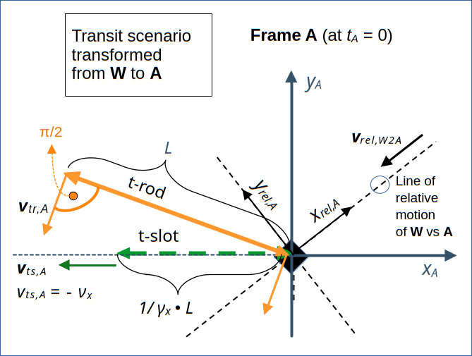
Illustration 2: Schematic representation of the transit scenario in out standard frame A at tA = 0. The drawing is based on the results of a LT of the data for the t-rod and t-slot from W to A – and a special (but very reasonable) selection of the t-rod’s velocity in W.
Conclusion
In this post we have applied the Lorentz Transformation to the setup data of a transit scenario for the rod and the slot. We have calculated both position data and components of the velocities of both the t-slot and the t-rod in our original standard frame A.
In the next post I will analyze our result in more detail, discuss consequences and perform a comparison of our two scenarios.
Stay tuned …