We continue our analysis of the rod/slot paradox in Special Relativity. So far, we have studied both a collision scenario and a transit scenario for the rod and the slot in two dimensions. Each scenario was consistently described by observers in various frames of reference, including frames attached to the moving objects themselves: In the transit scenario all observers see that the rod moves unharmed through the slot, while for the collision scenario all observers perceive an collision of the rod with an impenetrable plate surrounding the slot. No contradictions were indicated after a correct application of the Lorentz Transformation [LT].
So, what is the source of the paradox when it is presented in a standard way? Our scenarios were discussed in two different setup frames (called A and Z; see previous posts). Maybe, we unwillingly obscured some contradictions by this approach? To exclude this, a direct comparison of both scenarios in one and the same frame would be helpful.
Therefore, with this post we start comparing our two scenarios directly in common frames of reference, namely in both the setup frames A and Z for the scenarios. But we want to fulfill an additional major condition for a reasonable comparison.
Comparison with equivalent slots: Our objective is to perform such a comparison for fully equivalent slots in both scenarios. I.e. we want the length and velocity of the slot used in the collision scenario to be identical with respective properties of the slot in the transit scenario – in each frame chosen for the comparison.
This requires Lorentz Transformations [LTs] of one of the scenarios to the respective other frame, i.e. the transformation of the collision scenario from A to Z, and/or in reverse the transformation of the transition scenario from Z to A. But how can the frames Z and A be related in a reasonable way?
We will see in a minute that our recent work on the LT of the collision scenario to a frame W, which diagonally approached the setup frame A for the collision scenario, makes already half of the effort. W can be used to set up a transition scenario which is fully equivalent to what we defined for a frame Z. W can be used as a special Z moving in a defined way vs. the setup frame A for the collision scenario.
Previous posts:
- Post I: Special relativity and the rod/slot paradox – I – seeming contradictions between reference frames
- Post II: Special relativity and the rod/slot paradox – II – setup of a collision scenario
- Post III: Special relativity and the rod/slot paradox – III – Lorentz transformation causes inclination angles
- …
- Post XIII: Special relativity and the rod/slot paradox – XIII – Lorentz transformation of the collision scenario to a diagonally moving frame
- Post XIV: Special relativity and the rod/slot paradox – XIV – angle between colliding rod and slot in a diagonally moving frame
- Post XV: Special relativity and the rod/slot paradox – XV – velocities of colliding rod and slot in a diagonally moving frame
- Post XVI: Special relativity and the rod/slot paradox – XVI – perception of rod/slot collision in a diagonally moving frame
How to bring the scenarios together in one frame of reference?
We have used rather different frames A and Z to define our two scenarios. When you return to the 8th post of this post series, you will find that we used a special frame Z to define the transit scenario:
Frame Z was horizontally at rest regarding the slot, which moved vertically upwards. The rod moved horizontally, only, in Z, and approached Z‘s origin on Z‘s x-axis.
This setup was very different from the conditions set in a frame A for the collision scenario in the first posts. See the illustrations below for a comparison. How to bring the transit scenario in frame Z together with the conditions of the collision scenario defined in frame A?
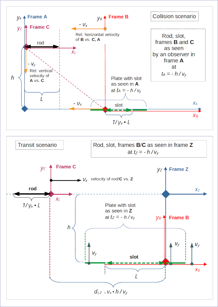
Illustration 1: Setup of the “collision scenario” and the “transit scenario” in two different reference frames, A and Z. It has not yet been defined how the scenarios and frames are related. A direct comparison of the scenarios’ initial conditions would require a common frame or a Lorentz transformation between the named frames.
Note that the basic velocities values νx and vy refer to the horizontal velocity of the slot and the vertical velocity of the rod, respectively, in our standard frame A. So far, we have used the same values for the objects in frame Z. But these velocities actually are free parameters of each scenario. It may happen that we have to adapt the values when we link the frames to each other.
Given the movements of the rod and the slot in A and Z, we are pushed to the following insights:
From the perspective of A, we need something like a diagonally moving frame to cover the situation given in Z: The origin would have to move horizontally and in parallel to the slot and at the same time follow the height level of the rod in A. The slot would hopefully move vertically upwards relative to such a frame.
I say “hopefully” because of potential relativistic rotation effects, which we have experienced before (Thomas-Wigner rotation). Nevertheless, this idea reminds us a lot of our frame W. We have already intensively studied the collision scenario there and know precisely what the initial conditions of the collision scenario look like in W. So, the question is:
Can we re-construct a transit scenario in our frame W, too? And maybe use a second rod/slot pair to account for the x-shift relative to the origin as given in Z?
As we know that velocities do not transform in the Newtonian way: What would the velocity components of a 2nd rod and a 2nd slot have to be in W to fulfill the conditions of the transit scenario?
Which orientation of the coordinate system of W is reasonable for setting up a transit scenario?
We have learned the hard way that the orientation of the coordinate system used in a frame of reference for 2-dimensional kinematic scenarios is a subtle question. We cannot simply “transfer” the orientation of lengthy objects as axes from A to a diagonally approaching frame A. According to the Lorentz Transformation [LT] the image of A‘s xA-axis is rotated by a bigger angle in W than in A relative to the line connecting the origins of A and W (during their mutual approach). To perform the LT from A to W (in its most simple form) we had to use (physically justified) coordinate systems having their x-axes aligned with the line of relative motion between the origins of both frames.
We have found that both the rod’s and slot’s orientations get modified by the so called “Thomas-Wigner rotation“ [TWR] as a consequence of the LT from a reference frame A to another frame that moves diagonally in A‘s coordinate system. We have furthermore derived that the rod and the slot of the collision scenario are rotated differently by the TWR-effect. This leads to a new question:
Which coordinate system of W (with what orientation relative to our moving objects) do we choose to base the aspired scenario comparison on a common ground?
Let us call the rod and the slot of the collision scenario “c-rod” and “c-slot“, and the respective objects of the transition scenario “t-rod” and “t-slot“.
The transit scenario is based on a vertically upwards moving slot. By applying the LT, we have already found that the velocity vector of the c-slot indeed has a perpendicular direction relative to the slot’s orientation in W. Furthermore, the c-slot’s orientation aligns with the Lorentz transformed image of the xA-axis in W (see the 12th and 13th post).
Let us therefore rotate the coordinate system of W such that its xW-axis has the same inclination to the line of relative motion (of A vs. W) as the slot in W. Let us call this axis xs,W. According to the preceding posts, we then arrive at the following situation at tW = 0 for the objects of the collision scenario:
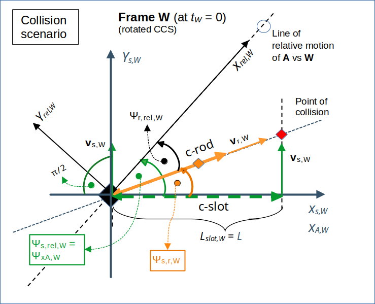
Illustration 2: The collision scenario as perceived in frame W at tW = 0. For details see the preceding posts. We choose a coordinate system with an xs,W-axis aligned with the c-slot’s orientation – and a ys,W-axis perpendicular to xs,W. The drawing is only schematic; the length of the objects and of the velocity vectors may not fit respective ratios given by the LT.
Note: The infinitesimally thin and impenetrable plates outside the borders of the slot are omitted in this and further drawings.
At some time tW < 0 we are closer to the original initial conditions in A, but as perceived by a W-observer. This is schematically indicated in the next drawing.
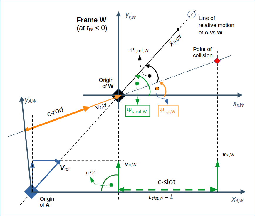
Illustration 3: The collision scenario as perceived in frame W at tW < 0. For details see the preceding posts. While the rod is moving vertically upwards, the rod shows a diagonally upward motion towards the origin of W !
Again: The drawing is only schematic; the length of the objects and of the velocity vectors may not fit respective ratios given by the LT.
Some readers may find it strange that the rod is moving diagonally upwards in this specific coordinate system of W. This is just a consequence of the fact that due to the LT the xA,W-axis (i.e. the image of the original xA-axis) and also the slot are rotated away by a larger (negative) inclination angle from the line of relative motion than the rod. It is the resulting (relatively bigger) rotation of the coordinate axes of our chosen coordinate system which causes an upwards movement in a respective coordinate system.
Note also that the image yA,W of the yA-axis is rotated outwards by a larger angle from the line of relative motion in W than in A. From the conditions in A we know that the left end of the rod resides on yA,W. So, for a time interval in W the rod must cover a larger distance in x-direction in our specific xs,W-direction than the origin of A.
For upcoming calculations we will, however, work with an axis ys,W that has an angle of π/2 with the xs,W-axis. Such a coordinate system is a standard Cartesian coordinate system for W.
Components of the velocity of A’s origin parallel and perpendicular to the slot in W
Let us have a look at the components of the velocity vector of the origin of A in W – relative to the coordinate system with the axes xs,W and ys,W. The absolute value of the relative velocity between two frames is an invariant of the LT. This is a basic ingredient in Special Relativity. (For experienced readers: This is consistent with the invariant scalar product of the 4-velocity with itself and the constant contribution of the first component).
Let us call the inclination angle of the slot vs. the line of relative motion (i.e. vs. the xrel,W-axis) Ψs,rel,W. Then, we get for the velocity components vx,A,sW parallel to the xs,W-axis and vy,A,sW perpendicular to the xs,W-axis :
I have used results from preceding posts to get these results. So, the origin of A moves with the same vertical component upwards in W as the slot itself.
Reconstruction of the transit scenario in W at tW = 0
How can we define a transit scenario (with a t-slot and a t-rod) in W that reflects the conditions in Z? The most important characteristics of the transit scenario in Z were:
- The slot (with proper length L) should move upwards with a constant velocity. We can easily achieve this by supplementing a second slot (“t-slot“), which moves parallel to the c-slot. We shift the t-slot to the left of W‘s origin to reflect the conditions we used in Z. The timing shall be such that the t-slot reaches the y-level ys,W = 0 at tW = 0.
- The rod (with proper length L) moved along the xZ-axis in Z and experienced a relativistic length contraction. In W this means that a t-rod should move along the xs,W-axis and approach the W-origin from the left with a constant velocity vtr,sW. At tW = 0 it’s right end must coincide with W‘s origin. The length contraction is given by the factor 1 / sqrt( 1– vtr,sW /c2).
We come up with the following situation at tW = 0:
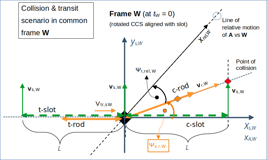
Illustration 4: Comparison of the transit scenario and the collision scenario in a common frame W at time tW = 0. At this moment the transit scenario (still) unfolds on the left side of the ys,W-axis, the collision scenario takes place on the right side of the ys,W-axis. The conditions of the transit scenario are equivalent to the setup in a frame Z, which we used in previous posts. The length of the t-rod is measured to be shorter than its proper length (Ltr,W < L) due to the relativistic length contraction. So, the ends of the t-slot (and assumed infinitesimally thin plates outside) can pass the t-rod vertically – at the last possible moment.
With these settings and regarding the transit scenario, frame W becomes fully equivalent to a frame Z which we used previously. The difference so far is a specific choice of the vertical velocity of the t-slot. We used the same velocity as derived for the c-slot by a Lorentz Transformation of the collision scenario from A to W. But the vertical velocity of the (t-) slot is is a free parameter of the transit scenario, anyway. For the choice of a horizontal velocity of the t-rod in W see a separate section below.
What is it that connects our scenarios?
Well, it is the same size and the same vertical movement of the c-slot and the t-slot. These slots are equivalent. Actually, we could even have used the (c-)slot of the collision scenario as the t-slot of in the transition scenario. This would only have changed later mathematical considerations, but no qualitative aspects.
Differences between the scenario conditions in the common frame W (equivalent to Z)
Looking at our illustration 4 we directly arrive at a first important conclusion:
Our collision scenario transformed from its setup frame A to a reference frame W (or Z) has profoundly different conditions at tW = 0 – and thus also at other time points before- than a transit scenario set up in the same frame W (or Z).
The most obvious difference between the collision scenario and the transit scenario in W at tW = 0 is the difference in the orientation of the rod. This is once again a solid indication that we have to take the initial angle between the rod’s and the slot’s orientations as a fundamental (free) parameter, which obviously distinguishes between scenarios that may have very different outcomes.
You cannot compare a 2-dimensional transition scenario (of a length contracted rod oriented in parallel to a slot) with a collision scenario without taking into account the effects of the Thomas-Wigner rotation when choosing certain observer frames. A collision scenario will in general exhibit different rotations of the rod and the slot in a setup frame for a transitions scenario when we use the same or a second slot with equivalent vertical movements there. Due to the Thomas-Wigner rotation the two scenarios are different and have different outcomes. But each of the scenarios is (hopefully) consistently described in different reference frames due to the properties of the LT.
Transformation of the transit scenario from W to A?
Another fruitful comparison between the transition scenario and the collision scenario would be one in the setup frame A for the collision scenario. For this purpose, we must transform the settings and data of our reconstructed transition scenario from W to A. This requires a clear choice of the velocities of the t-rod and the t-slot in W. All other conditions have already been defined by the relative movement of W vs. A.
Choice of the velocities of the rod and the slot for the reconstructed transition scenario in W
From the drawing above it may seem that we can choose the values of the velocities vts,W and vtr,sW freely within the bounds that they should be smaller than the velocity of light c. But as we want to make the collision scenario and the transit scenario comparable both in our frames W and A, we must fulfill some reasonable conditions:
- The c-slot and the origin of W (or Z) should move together. Both should approach the origin of A with the same horizontal velocity –νx. But this requirement is already guaranteed by our definition of the movement of W relative to A. We have derived the proper velocity vector vs,W and its components already via the Lorentz Transformation from A to W in the preceding posts. As the t-slot moves together with the c-slot we have already ensured a proper horizontal velocity for it also in A.
- There are two natural choices for the the horizontal velocity of the t-rod in W:
- We choose the projected velocity of A‘s origin on the xs,W-axis (see illustration 3) as the velocity vtr,sW of the t-rod.
- We attach the right end of the t-rod to the crossing point of image of A‘s y-axis. i.e. of the moving yA,W-axis, with the xs,W-axis.
These options are NOT the same, as we know already that the angle between the images of A‘s coordinate axes is not π/2. We choose the first option as it is mathematically easier to handle (though difficult enough , as we shall see). But, under this condition, we have to expect that the t-rod does not move downwards in A with its right end along yA-axis. But, at least, the movement of the t-rod in A will be correlated with the movement W‘s origin in A.
For mathematical operations regarding objects in W, I from now on refer to the chosen rotated coordinate system with the axes xs,W and ys,W. We choose the following components for the velocity vector vts,W of the t-slot in the reconstructed transition scenario:
and for the velocity vtr,W of the t-rod in W
Once again: The components have been given relative to the rotated coordinate system with the axes xs,W and ys,W. See some preceding posts for the origin of these particular component values. Remember that βx and βy refer to the absolute values of the slot’s horizontal velocity and the rod’s vertical velocity in our standard frame A.
These choices will indeed have some special consequences in A after a Lorentz Transformation of the transition scenario from W to A. In addition we expect also an impact of the Thomas-Wigner rotation on our objects. For the slot we expect an orientation parallel to the xA-axis and a horizontal velocity of –νx. But for the rod we need to perform an explicit mathematical calculation of the LT-results.
Conclusion
For a better understanding of the rod-slot paradox we need to perform comparisons of the collision scenario with the transit scenario in each of the respective setup frames. In this post we have seen that a collision scenario looks very differently from the transit scenario in the setup frame of the latter scenario – even if we use an equivalent or one and the same slot there.
The reason was the impact of the so called Thomas-Wigner rotation of elongated objects moving in two dimensions, when perceived and compared by observers in differently moving reference frames.
The next post starts with calculations regarding the transformation of a 2-dim transition scenario from the diagonally approaching frame W to our initial setup frame A for the collision scenario.
Stay tuned …