In this post series we study the rod/slot “paradox”. During the last two posts we got familiar with a “transit scenario” prepared in a special reference frame Z, where the rod and the slot moved along the x– and the y-axis, respectively. We have again derived a comforting result: Both observers in the setup frame Z and in a frame C co-moving with the rod measure and consistently describe a collision-free encounter of the rod and the slot: The slot moves through the slot.
This result was again due to a somewhat surprising effect of the Lorentz Transformation [LT] equations of Einstein’s “Special Theory of Relativity”. Analogously to the “collision scenario” we found a rotation of one of the diagonally moving objects (here of the slot) and a resulting inclination between the slot and the x-axis (and thus also the rod) in the rod’s frame – although the rod was aligned with the orientation of the slot in the setup frame. Basic reasons were the non-simularity of events after the application of the LT and a subtle combination of time dilation and length contraction effects for diagonal movements. This time the effects allowed for a transit of the rod through the slot. Or equivalently: The slot passed the rod diagonally with a proper timing to avoid any collision with the plate around the slot.
In this post we look at some details which an observer in the rod’s frame measures during the transit. This will prepare us for a further posts in which we will deal with a direct transformation of events seen by an observer attached to the slot to the frame of an observer attached to the rod.
Previous posts:
- Post I: Special relativity and the rod/slot paradox – I – seeming contradictions between reference frames
- Post II: Special relativity and the rod/slot paradox – II – setup of a collision scenario
- Post III: Special relativity and the rod/slot paradox – III – Lorentz transformation causes inclination angles
- Post IV: Special relativity and the rod/slot paradox – IV – consequences of an inclination angle in the slot’s frame
- Post V: Special relativity and the rod/slot paradox – V – perspective of the rod and aspects of the relative velocity between the rod and the slot
- Post VI: Special relativity and the rod/slot paradox – VI – consistency and the Lorentz Transformation between the slot and the rod
- Post VII: Special relativity and the rod/slot paradox – VII – no paradox for a collision scenario and consistency between all relevant LTs
- Post VIII: Special relativity and the rod/slot paradox – VIII – setup of a transit scenario with the rod moving through the slot
- Post IX: Special relativity and the rod/slot paradox – IX – transit scenario and measurements by an observer co-moving with the rod
Angles and special points on the slot
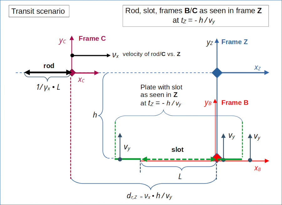
Analogously to the collision scenario we can identify some special points and a related distance sequence along the x-axis in the frame of the object that moves horizontally in the setup frame. In the “transit scenario” (see the 8th post of this series) this object is the rod. From the perspective of the rod the slot moves diagonally upwards to meet the rod’s right end at tC = tZ = 0.

Illustration 1: Setup of the “transit scenario” in reference frame Z. The rod moves horizontally with velocity –νx, and its right end meets the the right end of slot, which moves upwards with velocity vy, at the origin of frame Z at tZ = 0. Frame C co-moves with the rod and frame B co-moves with the slot.
For details, notation and quantities see the previous posts in this series. We employ the usual β– and γ-factors characterizing the relative motion of inertial frame versus each other.
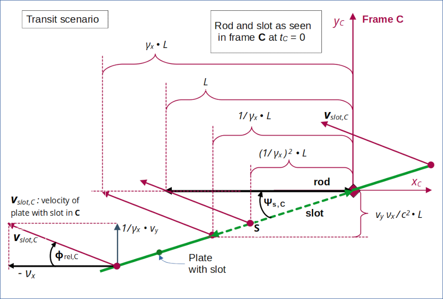
In the 9th post we have derived the results of the Lorentz Transformation for key event coordinates related to the rod’s and the slot’s end points at tZ = tC = 0 in the rod-attached frame C. The following schematic drawing displays some critical points in frame C and their motion during the transit (or equivalently during the passage of the slot across the rod) :

Illustration 2: Special points and distances in frame C at the start of the transit (= the slot passing the rod) without collision. The component of the slot’s velocity in yC-direction in frame C differs from vy (measured in frame A) due to time dilation effects.
Again, we observe a remarkable sequence of distances controlled by the γx -factor. Compare this to the results derived in posts III and IV for the collision scenario.
In the last (9th) post we have already shown that the slot’s left end can be characterized by an event E2 at tC=0:
The length of the slot in C can be calculated by using Pythagoras as
As a consequence we can describe the angle Ψs,C between the slot and the xC-axis by the following relations:
We also have found that the left end of the slot reaches the line yC = 0 at a point (xC, yC) = (- γx • L, 0)
Let us also evaluate the movement of a point “S” on the slot with and xC-distance of γx2 • L to the left of C‘s origin. The vertical distance ΔyS of this point to the line yC = 0 at tC = 0 is given by
This means:
The time ΔtS to cross this vertical distance is
After this time interval the point S reaches the xC-coordinate
(on the line yC = 0) as depicted in illustration 2.
Velocity of the slot and respective components
The velocity of the slot vs. the rod has two different components, namely vs,x,C = – νx in xC-direction and vs,y,C in yC-direction. We write this in “vector notation” as a vector vslot,C
Pythagoras gives us the length of the vector and thus the absolute value of the velocity of the slot
The angle Φrel,C between the xC-axis and the slot’s velocity is given by
Conclusion
The attentive reader has, of course, noticed that the above results for absolute values of distances and inclination angles in the rod’s frame of our transit scenario are completely analogous to similar results derived for the collision scenario (in the slot’s frame there).
This indicates already that a direct Lorentz Transformation e.g. from the slot’s frame B to the rod’s frame C will give us values consistent with the results of a LT between frame Z and frame C. This would prove full consistency between the descriptions of a collision-free transit of the rod through the slot by observers in frames Z, B and C. Thus, any potential paradox will disappear for the transit scenario, too.
The Lorentz Transformation from frame B to frame C will be the topic of the next post.
We expect again a combination of spatial rotations with a 1-dimensional Lorentz transformation along the line of relative motion between the rod and the slot.
Stay tuned …