We are on a good way to resolve one of the length contraction paradoxes in Special Relativity – the rod-slot paradox – with the help of some rather simple considerations and some simple math. We have already found a consistent description of a collision scenario by observers in three different inertial frames. We have used Lorentz Transformations [LTs] from a setup frame A to a frame B, moving with the slot, and another LT from frame A to a frame C, moving with the slot. We now prove consistency by a transformation of rod and slot coordinates measured in frame B to the diagonally approaching frame C attached to the rod.
By looking into transformations between the measurements of observers attached to physical objects we get deeper to the heart of Special Relativity [SR]. We now (almost) forget what we know about the overall scenario described in a special setup frame A. Instead we refer to local observations as seen by the physical objects, the slot and the rod, in relative motion versus each other. And then we translate the observations from one object’s perspective to the perspective of the other object only by referring to the measured relative motion of the objects against each other.
Previous posts:
- Post I: Special relativity and the rod/slot paradox – I – seeming contradictions between reference frames
- Post II: Special relativity and the rod/slot paradox – II – setup of a collision scenario
- Post III: Special relativity and the rod/slot paradox – III – Lorentz transformation causes inclination angles
- Post IV: Special relativity and the rod/slot paradox – IV – consequences of an inclination angle in the slot’s frame
- Post V: Special relativity and the rod/slot paradox – V – perspective of the rod and aspects of the relative velocity between the rod and the slot
Hurdles, relative motion and objectives
The Lorentz transformations from A to B and from A to C were rather easy to handle as we dealt with
- movements of the target frames B and C along the xA-axis and the yA-axis of our setup frame A, respectively,
- and with an orientation of both the rod and the slot parallel to the xA-axis.
The situation between frames attached to the rod and to the slot is more complicated as we must deal with diagonal movements of the rod vs. the slot and vice versa. I have used the plural “movements” intentionally, as these movements look a bit different in B and C.
What do we mean by diagonal movements? Redefinition of the orientation of coordinate systems …
Let us briefly reflect upon what we can refer to when we assume fully relative perspectives of our objects in question and the perceptions of related observers. So far, we have a bit misused the Cartesian coordinate system of a particular frame A to define (aligned) orientations of the x-axes of frames B and C.
But in the best sense of “relativity” between observers attached to the rod and the slot we should do something with a more physical meaning. From the perspectives of such observers we only experience two elongated 1-dimensional objects moving against each other in an empty globally flat 2-dimensional Euclidean space. We should best get rid of frame A and restrict our considerations to slot and rod-related observers and respective coordinate systems.
The first thing we have to become clear about is the fact that the term diagonal has no absolute meaning. It only has a meaning with respect to a selected coordinate system. But in Special Relativity there are no absolute coordinate systems. What we, however, can do is the following: We define the orientation of a Cartesian coordinate system with respect to some selected physical object, or to some measured physical quantity as the objects’ relative velocity versus each other.
Regarding the selection and orientation of a coordinate system in the case of an observer co-moving with the slot (frame B), it is natural to refer to the slot itself: We fix the origin of his coordinate system to the slot’s left end and define the xB-axis to be aligned with the slot.
In the case of frame C for an observer co-moving with the rod, we instead refer to the rod: We align the xC-axis of frame C as aligned with the rod itself, and fix the coordinate system’s origin to the left end of the rod.
Both definitions have a clear meaning now – without any reference to a frame A. For each of our coordinate systems, we know exactly now, what we mean when we use the word “diagonal”:
In frame B we have a situation where the rod approaches the slot along a track that has an inclination angle Φrel,B with the xB-axis aligned with the slot. In frame C instead, we see the slot approaching the rod along a track that has an inclination angle Φrel,C with the xC-axis aligned with the rod.
A second important point is: Special Relativity [SR] does not guarantee that these spatial angles are the same. Nor does it guarantee us that any inclination between the rod and the slot as seen in one reference frame might be the same in another. But SR gives us a toolset (namely the Lorentz Transformation equations) to calculate what an observer in frame C will see based on measurements and observations of an observer in frame B.
Side remark: Some experienced physics students may argue that an angle is a scalar and that scalars should be kept up by relativistic transformations. However, SR deals with vectors and tensor quantities in 4-dimensional space-time. Our angles refer to the 3-dimensional spatial sub-space, only, and here the LT does affect scalar products both due to length contraction and side effects of time dilation.
Perspectives and perceptions
The following drawing shows the situation experienced in frame B:
Rod’s movement as seen in frame B
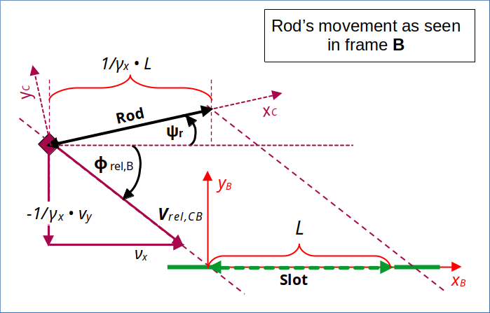
Illustration 1: The rod’s diagonal movement as seen from the slot and frame B
During the calculations below we take this as given (= measured) conditions. In particular we accept the inclination angle Ψr = Ψrod,B as given. We forget that we have derived things by a LT from another frame A.
Our question is instead: What can we say about observations in frame C if the conditions in B are given as displayed?
In the previous post V we have already debated that observers co-moving with the rod may have the following perception of the slot’s movement.
Slot’s movement as seen in frame C
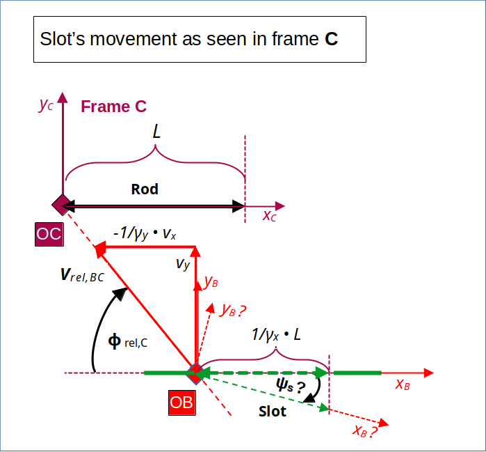
Illustration 2: The slot’s movement as seen from the rod and frame C (according to a LT from frame A to C; see post V)
The angle ΨS is marked with a question mark to indicate that this is a quantity which we have to derive via the LT. But we have a prediction for it.
Objective: Reproduce previous predictions by a LT from frame B to frame C
The xC-axis of the standard coordinate system of frame C for a description of spatial coordinates of moving objects is aligned with the rod. For our special collision scenario (see post II) previous independent calculations (see post V) have predicted that the slot should appear aligned with the rod’s orientation in frame C and the standard xC-axis there:
We also expect that the slot’s length Lslot,C in C fulfills:
In addition we know from our scenario setup and from the LT between A and C:
All of these equations should be reproduced by a direct LT from B to C – guided by the relative velocity between the rod and the slot. This is the main objective of the following steps.
When you think about it in the light of what we already know this is not a trivial endeavor. Instead it corresponds to a major consistency check for the equivalence of the collision prediction between different inertial frames.
Hurdle: The relative velocity vector has different inclination angles with the presently chosen xB– and xC-axes in our frames B and C
The 5th post of this series provided us with some formulas regarding
- the spatial components of the relative velocity vector vrel,CB between the rod and the slot in frame B,
- the spatial components of the relative velocity vector vrel,BC between the slot and the rod in frame C,
- respective inclination angles of vrel,CB and vrel,BC vs. the x-axes of B and C, respectively
- and the gamma-factor related to the absolute value of the relative velocity.
Due to a different time dilation between A and B in comparison to the time dilation between A and C, we got different measurements
- for the inclination angle between the vector of relative velocity vrel,CB with the slot and the xB-axis in frame B
- and for inclination angle between the vector of relative velocity vrel,BC with the rod and the xC-axis in frame C.
This did not surprise us too much as we have shown already (see posts III and IV) that the rod appears rotated vs. the xB-axis in the slot’s frame. We take it therefore as given that the inclination angles of the relative velocity vector with the x-axes are different in B and C, i.e. |Φrel,B| ≠ |Φrel,C|:
This will make our life a bit harder.
Suitable spatial coordinate systems for the frames attached to the rod and the slot
We use the abbreviation “ECS” for a Cartesian coordinate system (in our flat Euclidean spaces of Special Relativity). While our presently chosen ECS for an observer moving with the slot – with the xB-axis aligned with the slot – is well defined, it is not really helpful for performing the LT between the slot and the rod on our level of our mathematical discussion. The familiar form of the LT given in the 3rd post of this series requires that the relative velocity is aligned with the x-axes of the moving reference frames in question. This is definitely not the case for the presently defined B– and C-frames.
To be able to use the familiar simple form of the Lorentz Transformation, we have to consider spatial ECSs for B and C, whose x-axes are aligned with the relative velocity vector as perceived in each of the respective frames. We call such an ECS with an orientation along the line of relative motion a “rotated ECS” below, because it is rotated vs. the standard ECS whose orientation is given by the slot (or the rod).
Furthermore, we have to evaluate the components of the spatial vectors to event locations in each of the rotated coordinate systems with respect to the rotated x– and y-axes there. I have illustrated this in the following drawing.
Projections of rod and slot extensions onto axis of rotated ECS in B
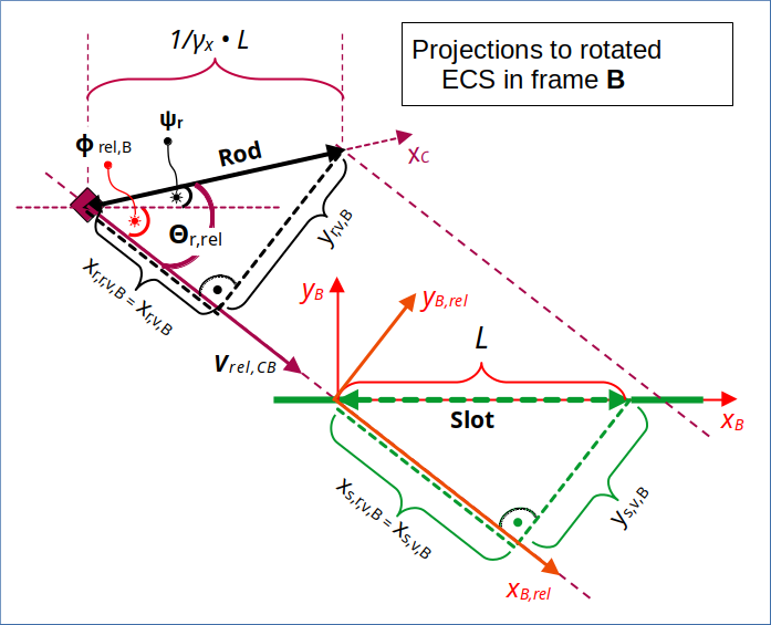
Illustration 3: Rotated ECS in frame B with x-axis xB,rel aligned to the relative velocity vector vrel,CB – and projections of rod and slot onto the rotated coordinate axes
Our approach for the LT from B to C therefore consists of the following steps:
- Determine the components of the relative velocity vector of the rod in the slot’s frame B and its respective angle Φrel,B with the xB-axis.
- Create an ECS with an x-axis xB,rel aligned with the relative velocity vector.
- Perform a projection of the spatial vectors describing the position of rod and slot-related events to get components parallel and perpendicular to the relative velocity vector. This corresponds to determining the spatial event coordinates in the rotated ECS.
- Apply the standard Lorentz Transformation to the event-coordinates in the rotated ECS (with a gamma-factor derived from the absolute value of the relative velocity).
- Re-transform the resulting coordinates parallel and perpendicular to the relative velocity vector in frame C to coordinates of the standard ECS in C, whose xC-coordinate axis is aligned with the rod.
In a later post we will perform an analogous reverse transformation from C to B.
Calculation steps in rotated ECS of frame B
According to our previous post V, the components, the length and the gamma-factor for the relative velocity vector between frames C and B (i.e. between the rod and the slot) are given by:
Here we have used the velocity values νx and vy of our collision setup (see post II). But νx, γx and also the velocity vr,y,B = 1/γx • vy have a clear meaning in frame B – independent of any frame A.
Remember that we have already shown (in the 5th post) that the absolute value of vrel is, of course, the same in both frames B and C, and that the respective gamma-factor has the given simple form.
With L being the proper length of both the rod and the slot, the values of the angles Φrel,B and Ψr are given by (see posts IV, V):
I have used the absolute values of the angle Φrel,B, because we had defined it to be negative in post V. For the rest of our calculations below, we focus on absolute angle values. Lrod,B is the total length of the rod as seen in frame B (see post IV for details).
Looking at the diagrams above we see that the projections of the rod and the slot parallel and perpendicular to the relative velocity vector are given by
At tB = tC = 0 the left ends of the rod and the slot coincide with the origin of the coordinate system of B (see posts I, II). With the help of some elementary trigonometry
we get for the projected components of the spatial vector to the right end of the rod at tB = 0:
Rod’s vector components parallel and perpendicular to relative velocity vector
For the slot’s components we get:
Slot’s vector components parallel and perpendicular to relative velocity vector
Event selection for the transformation of the rod’s coordinates
We now have to consider which events we select for the Lorentz transformation to frame C. The events for the rod’s left and right ends, [xr,l,v,B, yr,l,v,B, tr,l,v,B] and [xr,r,v,B, yr,r,v,B, tr,r,v,B], respectively, should be chosen such that they get transformed to simultaneous time coordinates tr,r,v,C = tr,l,v,C .
Why is this? Because the observer in C naturally watches or measures different spatial data for the rod (or the slot) there at the same point in time. We had defined this as a condition for the perception of a spatial situation by an observer. Our reference data derived in post V were, therefore, based on the simultaneity of measurements in C. For reasons of simplicity we choose our time coordinates to be tC = tB = 0 .
The coordinates of some distinct event at a distance xv,B along the rotated axis xB,rel occurring at time tv,B will be transformed to respective coordinates in frame C as
So, if we want to achieve tv,C = 0, we must request :
Let us mark the xB,rel -position of the rod’s right end at such shifted time (tv,B = tr,v,B) by a hat:
But, on the other side, any point of the rod (!) having a coordinate xr,v,B at tB = 0 will at a later time tr,v,B have an xB,rel -coordinate (in B) given by
We must, of course, use this specific coordinate for a suitable event to fulfill the condition for its transformed time coordinate to be tr,v,C = 0. Filling in tr,v,B gives us
We use again a short notation for events: Ev ∼ [xv,B, yv,B, tv,B]B. However, this time we refer to coordinates in the rotated ECs with the xB,rel and the yB,rel axes. I have indicated this by a sub-script “v”.
Let us call the x-, y-, t-coordinates of events regarding the left and the right ends of the rod in the rotated coordinate systems of frames B and C
xr,l,v,B , yr,l,v,B , tr,l,v,B and xr,r,v,B , yr,r,v,B , tr,r,v,B
and
xr,l,v,C , yr,l,v,C , tr,l,v,C and xr,r,v,C , yr,r,v,C , tr,r,v,C,
respectively. We want to transform from the rotated ECS in B to a rotated ECS in C.
Our considerations above mean that we should select the following events for the left end of the rod (Evr,l) and the right end of the rod (Evr,r) in frame B to get respective spatial coordinates in frame C at tC = 0:
Event selection for the transformation of the slot’s coordinates
For the slot things are a bit simpler because the slot does not move in frame B. The relevant events are:
Transformation of rod-coordinates from frame B to frame C
Before we perform the Lorentz Transformation from B to C, let me remind you that we found the following value for the angle Φrel,B between the standard xC-axis and the vector of the relative velocity in C in post V:
See the following drawing:
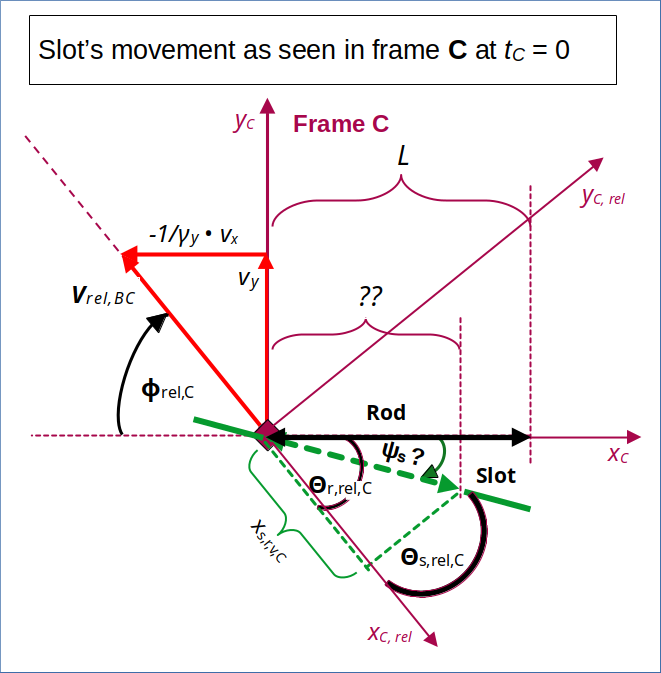
Illustration 4: Rotated ECS in frame C with x-axis aligned to the relative velocity vector vrel,BC – and projections of rod and slot to the rotated coordinate axes
We get the following transformed coordinates parallel and perpendicular to the relative velocity vector in frame C:
Note again that these coordinates are defined in the rotated coordinate system in C with an x-axis (= xC,rel -axis) parallel to the relative velocity vector, there. These are not the coordinates given in the standard coordinate system with an xC-axis parallel to the rod.
From the results above we can derive two interesting relations – one for length of the rod in C (here via the components in the rotated coordinate system)
and one for the cosine of the angle Θr,rel,C between the component xr,l,v,C parallel to the relative velocity vector and the position vector to the endpoint of the rod in C:
In the sense of our initial argumentation, this is the prediction for the orientation of the standard xC-axis of an ECS coupled to the rod in C. We still have to prove that the slot transforms such that it is perceived to be aligned with the rod and thus also with the standard xC-axis in C. This is one of our basic consistency test for our collision scenario – based on a comparison of data measured by observers attached to the slot and the rod.
Consistency with data derived from frame A
Although we focus on a transformation between B and C, let us nevertheless briefly compare our result to a corresponding result of an independent LT from frame A to C. Indeed, we had seen in post V
This means that the angle Ψrod,C between the rod and the standard xC-axis indeed becomes 0:
Our complicated transformation from frame B to C via the relative velocity between rod and slot confirms that the rod (in a frame C co-moving with the the rod) is indeed oriented along the standard xC-axis there and that it has the length Lrod,C = L !
This may seem trivial, but it is not. Actually, we have in parts shown that Lorentz Transformations
- between a frame A and a frame B,
- between a frame A and a frame C
are consistent with a more complex transformation
- between frame B and frame C approaching each other diagonally.
Transformation of slot-coordinates from frame B to frame C
Let us now look at the transformation of the slot’s coordinates. Our hope is that the transformed coordinates will indicate
- that the slot is oriented in parallel to the rod in C
- and that the slot is too short in C to let the rod pass through at tC = 0.
I leave it to the reader to go through the full LT for the component parallel to the relative velocity vector. I just employ the usual length contraction formula as we know that we transform to simultaneous time coordinates in C – and therefore transform results of length measurements between our inertial systems.
Thus, we get the following value for the length Lslot,C of the slot in frame C – by using Pythagoras for the components of a respective position vector in the rotated ECS in C (with an x-axis parallel to the relative velocity vector):
What about the orientation? What is the angle Θs,rel,C between the slot and the xrel,C -axis of the rotated coordinates system in C?
It follows
We obviously get an alignment of the slot with the rod and thus also with the standard xC-axis in frame C! And, as we had hoped for, the length of the slot is reduced due to length contradiction as previously predicted by an independent LT from frame A to frame C.
This means that a transformation from frame B to frame C consistently predicts a collision of the rod with the slot’s surrounding plate (exactly at the expected leftmost collision point on the rod). See the following drawing:
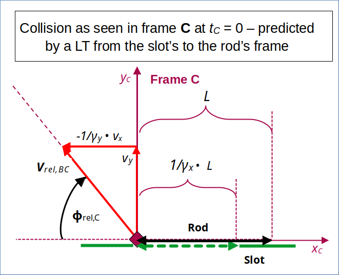
Illustration 5: Collision as seen by the rod – predicted by a LT from the slot’s frame to the rod’s frame
Conclusion
All in all we have shown that Lorentz Transformations between 3 inertial systems consistently reproduce a collision between a rod and a slot (with the same proper length) by a relative movement in two dimensions – if the setup is explicitly done such that a collision occurs in an easily analyzable frames A and C:
- Frame A: Setup for a collision between a rod moving vertically along the yA-axis and a slot moving horizontally along the xA-axis.
- LT from frame A to frame B (co-moving with the slot): A collision is predicted due to a diagonal movement of the length contracted rod, which shows an inclination angle Ψr with the xB-axis. The collision point on the rod with the plate surrounding the slot is defined by a proportional length contraction of the interval between the left end and the collision point in frame A.
- LT from frame A to frame C (co-moving with the rod): A collision is predicted very similar to the one described in frame A, but shifted vertically into the rod’s coordinate system.
- LT between frame B (co-moving with the slot) and frame C (co-moving with the rod): A collision is consistently predicted in C when we perform a LT from B to C along the vector of relative velocity.
The only missing thing now for complete consistency is a transformation from frame C to frame B. This is is a pretty interesting operation because we could have defined the initial conditions supporting a collision also directly in frame C (instead of in A). Wat we have to show is that such a setup in the rod’s standard frame C inevitably leads to an inclination of the rod versus the slot perceived by an observer attached to the slot.
In a way this is just a reversal of what we have done in his post. I will show the basic steps in the next post:
But, we now can be very confident that there is no paradox at all for the case of an explicit collision scenario. The reader, which has followed my line of thought so far, has, of course, already identified the problematic point, which lead to the wrong claim of a paradox in the first place.