In our post series about the rod/slot “paradox” in Special Relativity we presently study a “transit scenario“. In this scenario the rod passes the slot unharmed due to a clever combination of initial conditions in a setup frame Z. We have already studied the Lorentz Transformation [LT] of key event coordinates from the setup frame Z to a reference frame C co-moving and aligned with the rod. Observers in both frames consistently agree upon the fact that the rod moves through the slot without a collision with the slot-surrounding plate. But to make any potential paradoxes disappear we yet have to prove that a direct Lorentz Transformation [LT] between a frame B co-moving with the slot to the rod’s frame C also produces consistent transit results. Such an LT is the endeavor of this post.
Previous posts:
- Post I: Special relativity and the rod/slot paradox – I – seeming contradictions between reference frames
- Post II: Special relativity and the rod/slot paradox – II – setup of a collision scenario
- Post III: Special relativity and the rod/slot paradox – III – Lorentz transformation causes inclination angles
- Post IV: Special relativity and the rod/slot paradox – IV – consequences of an inclination angle in the slot’s frame
- Post V: Special relativity and the rod/slot paradox – V – perspective of the rod and aspects of the relative velocity between the rod and the slot
- Post VI: Special relativity and the rod/slot paradox – VI – consistency and the Lorentz Transformation between the slot and the rod
- Post VII: Special relativity and the rod/slot paradox – VII – no paradox for a collision scenario and consistency between all relevant LTs
- Post VIII: Special relativity and the rod/slot paradox – VIII – setup of a transit scenario with the rod moving through the slot
- Post IX: Special relativity and the rod/slot paradox – IX – transit scenario and measurements by an observer co-moving with the rod
- Post X: Special relativity and the rod/slot paradox – X – details of the transit scenario as seen by the rod
Working plan
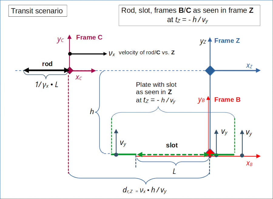
We closely follow the steps we have already learned in the context of the collision scenario, but apply them to the transit scenario. Note that both rod and slot have a proper length L. The reduced length of the rod assumed in frame Z is due to the relativistic length contraction.

Illustration 1: Setup of the “transit scenario” in reference frame Z. For details see the previous posts. Both rod and slot have a proper length of L at rest in their attached frames C and B, respectively. In frame Z the length of the rod is measured to be 1 / γx • L due to relativistic length contraction.
- We first establish the perception of an observer in the slot’s frame B. We write down the components of the relative velocity between the rod and the slot.
- We calculate the inclination angles of the velocity vector with the x-axes of frames B and C. We expect these angles to be different due to the impact of time dilation.
- Afterward we project selected spatial position vectors onto the line of relative motion in frame B. This process is equivalent to a spatial rotation of the spatial Cartesian coordinate system [ECS] of B such that the x-axis of the rotated ECS coincides with the line of relative motion. The projection gives us the spatial coordinates in the rotated spatial ECS.
- We apply a 1-dimension Lorentz Transformation between the rotated ECS in B and a similarly rotated ECS attached to the rod in C. This LT is completely controlled by the absolute value of the relative velocity between the rod and the slot.
- Eventually, we calculate and check inclination angles vs. the xC-axis and values for the rod/slot lengths resulting from the transformed slot’s and rod’s end point coordinates in the rod’s frame C.
Perception of the rod’s transit by an observer in the slot’s frame
The perception of an observer in frame B is relatively easy to derive as the relative motion between frame B and frame Z occurs along the yZ-axis of frame Z. The relative velocity of B vs. Z is vy.
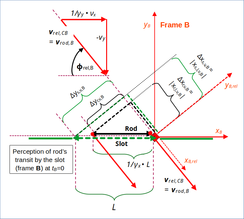
The orientations of the rod and the slot are perpendicular to the line of the relative motion of the slot vs. frame Z. Therefore, the lengths of the rod and slot are not affected by any (further) length contraction effects. The x-coordinates of the end-points of these objects are not changed by a LT along the y-axes for a given point in time and related events. To perform the LT we just have to interchange the meaning of x– and y-axes in the standard formulas of the Lorentz Transformation [LT] (given in the 3rd post). The rod will be measured by an observer in B to have the same length as measured in Z. Also the orientation of the rod vs. the x-axis will not change by the LT from Z to B.
However, time dilation between Z and B has an impact on the transformation of the velocity of the rod (measured in Z as νx) from frame Z to B. An observer in B will measure a reduced velocity vr,x,B = 1 / γy • νx.
The relative vertical velocity component of the rod vs. the slot is, of course, –vy :
Let us write down the spatial components of the relative velocity vector vrod,B of the rod vs. the slot as seen by the slot in our simple vector notation (vr,x,B, vr,y,B). The bold v indicates a vector :
This, of course, is also the relative velocity vrel,CB of frame C vs. frame B as seen by an observer in frame B
The length of the slot in frame B obviously is L, and the length of the rod remains 1 / γx • L after the LT to frame B. We arrive at the following drawing which characterizes the transit perception of an observer in B at tB = tZ = 0:

Illustration 2: Perception of the transit by an observer in frame B co-moving with the slot. The rod approaches diagonally and moves through the slot at tB = 0. Rod and slot are oriented parallel to each other. Th point in time tB = tZ = 0 is the last possible moment for the transit of our infinitesimally thin objects. Note that the rod has the same contracted length in frame B as in Z. A rotated ECS is indicated by the dotted axes named xB.rel and yB,rel. I have also depicted required projections onto the rotated coordinate axes.
Due to our timing of the rod/slot encounter, the transit of the rod occurs at the last possible moment. We have assumed infinitesimally thin objects in yZ– (and zZ-) direction. The drawing displays projections of the slot and the rod onto the line of relative movement as seen in frame B. The angle Φrel,B between the xB-axis and the rod’s velocity is given by
We know already that it is different from the corresponding angle Φrel,C in frame C (see below and the previous 9th post of this series):
See the 5th post of this series for a corresponding (inverse) relation for the collision scenario – and, please, note that frames B and C have changed roles.
Different inclination angles of the relative velocity vector with respect to the x-axes of the rod/slot frames
Before we apply a LT from frame B to C let us gather some more information about the transit scenario. We remember the results of the LT from Z to C (see the 10th post):

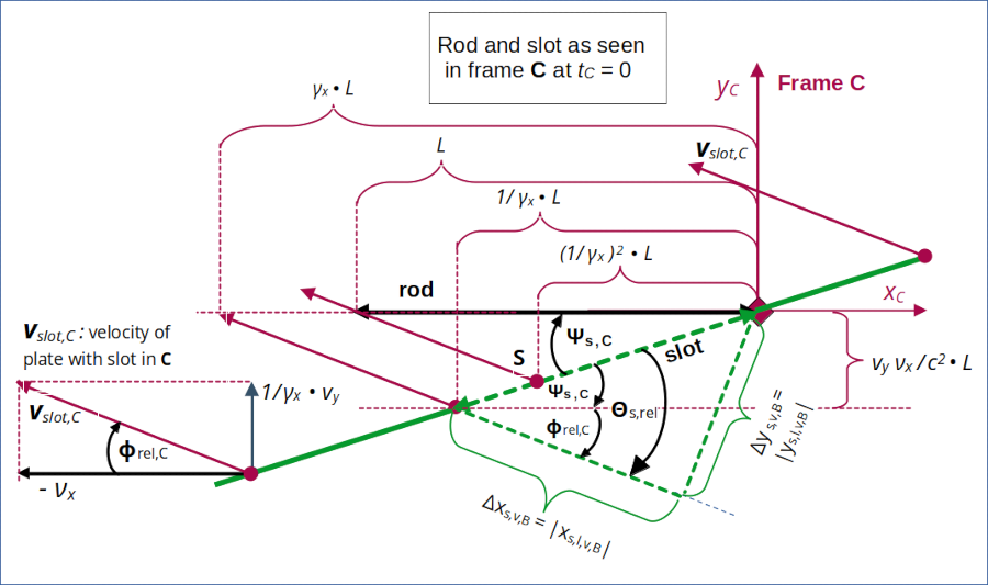
Illustration 3: Perception of the transit scenario by the rod – according to a LT from frame Z to frame C. See the 10th post of this series for more details.
The absolute value of the relative velocity is given in our frames C and B by
It is easy to show that these velocity values are identical:
We also know
with
Cosine and sine values for Φrel,B and Φrel,C are given by :
The length of the slot in frame C has been found (see the previous 10th post) to be given by
The angle of the slot with the xC-axis is given by
These values should be reproduced by a direct LT from frame B to C.
Lorentz Transformation of the slot’s coordinates from frame B to frame C
We start with the transformation of the slot’s end point coordinates. In B the slot does not move. We need the coordinates of the outer left end-points of the projection of the slot onto the line of relative motion (of the rod) in B. This line segment is parallel to the line of motion and the relative velocity vrel,CB. The x-coordinate value xs,l,v,B of its left end-point in the rotated ECS is
The projected line segment vertical to the line of relative motion has an end-point at the coordinate ys,l,v,B (in the rotated ECS), which is given by
The lengths of both line segments are given by the absolute values of the endpoint coordinates:
The LT with vrel along the line of motion to frame C leads to a simple length contraction, because the slot is at rest in B. You can derive this in detail via the LT formulas of the 3rd post. We take the simple contraction shortcut here. The corresponding result for the transformed coordinates is:
The projected vertical line segment remains of course unchanged by a LT between coordinate systems with x-axis along the line of relative motion:
From these data we can calculate the length of the slot in frame C as given by the LT:
Hence
Good! What about the angle of the slot Ψs,C with the x-axis according to our direct LT? In frame C we have to calculate the angle by the following formula (see illustration 2):
The angle Θs,rel is the angle between the slot and the line of relative motion. It is given by
With the other values given above we get
Which is correct! We obviously have reproduced the length and the inclination angle which we previously found by a LT from frame Z to frame C. The slot appears rotated in frame C and its total length is somewhat shorter than L.
So, a LT from B to C transforms our key coordinate values for the slot just as we expected it from our setup. The measurements in Z, B, C for the slot’s length and orientation are fully consistent.
Lorentz Transformation of the rod’s coordinates from frame B to frame C
For the transformation of the rod we proceed almost analogously. But this time we have to take care of the fact that the rod moves in frame B. So we need to find the coordinates of an event which transforms its time coordinate to tC = 0. The standard projection gives:
And:
A short calculation tells us the corrected tB– and xB-coordinates, tr,l,v,B2 and xr,l,v,B2, respectively, for the rod’s left end to fulfill
On the other side – due to the movement of the rod with vrel along the line of relative motion:
Hence
Thus, at tC= 0, we get via the LT :
And:
For the rod’s length in C, as given by the LT, we get:
And for the angle with the xC-axis :
This is exactly what we should get (according to a previous LT between frames Z and C)!
Direct Lorentz Transformation from frame C (rod) to frame B (slot)
The LT from frame B to frame C can be done analogously. I leave this to the reader. See also the calculation steps in similar posts for the collision scenario. Eventually, the LT from C to B will give you consistent data and descriptions of the transit.
Conclusion – no paradox for the “transit scenario”
What have we shown for our “transit scenario”? We have proved that LTs from the setup frame Z to frames B (co-moving with the slot) and C (co-moving with the rod) provided event data and spatial coordinates consistent with the data of direct LTs from frame B to frame C and vice versa.
All observers in all critical frames tell us the same message: If the rod moves through the slot in one frame, observers in other inertial frame will also find a smooth, collision-free transit. There is no paradox for the transit scenario! Just as there was no paradox for the collision scenario, which we analyzed in the first posts of this series.
The forthcoming posts of my series will point out that our selected scenarios, though seemingly similar, reflect very different initial conditions. We will also discuss why the order of certain symmetry operations and a related non-commutativity is crucial. This will lead us to the deeper causes of rod/slot “paradoxes” – namely a false representation of the initial conditions leading to a comparison of basically incompatible scenarios.
However, in the next post
we will first investigate what happens to coordinate axes when we transform them to a diagonally approaching frame. This will lead us to the question how we in general choose a proper x-coordinate axis in a diagonally moving frame for our two scenarios. This will later help us to transform our collision scenario into the setup frame of our transit scenario.