In the course of this series on the rod/slot paradox in Special Relativity we now start to analyze a scenario in which a rod moves through a slot. We have called such a scenario a transit scenario. I want to show that an inclination of the slot against the x-axis (and the rod) measured in a frame co-moving with the rod removes any potential paradox. To achieve this objective we apply a Lorentz Transformation [LT] to get coordinates of key events as measured by an observer co-moving with the rod.
Previous posts:
- Post I: Special relativity and the rod/slot paradox – I – seeming contradictions between reference frames
- Post II: Special relativity and the rod/slot paradox – II – setup of a collision scenario
- Post III: Special relativity and the rod/slot paradox – III – Lorentz transformation causes inclination angles
- Post IV: Special relativity and the rod/slot paradox – IV – consequences of an inclination angle in the slot’s frame
- Post V: Special relativity and the rod/slot paradox – V – perspective of the rod and aspects of the relative velocity between the rod and the slot
- Post VI: Special relativity and the rod/slot paradox – VI – consistency and the Lorentz Transformation between the slot and the rod
- Post VII: Special relativity and the rod/slot paradox – VII – no paradox for a collision scenario and consistency between all relevant LTs
- Post VIII: Special relativity and the rod/slot paradox – VIII – setup of a transit scenario with the rod moving through the slot
The readers who have followed my line of argumentation for proving consistency between the descriptions of a rod/slot collision in various inertial frames have certainly got an idea already, of what is going to happen. Our intuition tells us that a systematic time shift of distanced events measured by moving observers will cause an inclination angle of the slot versus the x-axis (and thus versus the slot, too) in a frame co-moving with the rod. The additional diagonal movement of the slot vs. the rod in the rod’s frame of reference may help to guarantee a collision-free rod-slot encounter.
The transit scenario
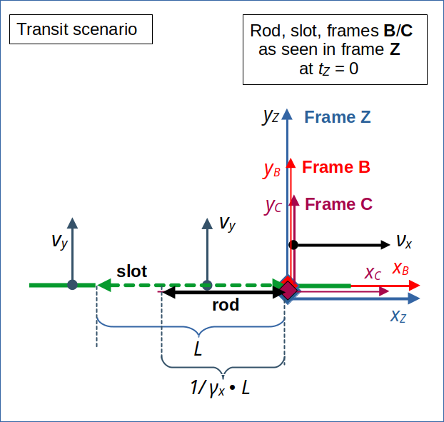
For the setup of our transit scenario see the previous 8th post in this series. In a frame Z, a plate with a slot moves vertically upwards along the yz-axis with constant velocity vy. At time tZ = 0 the slot’s right end meets the right end of a rod moving horizontally with constant velocity νx along the line yZ = 0. Slot and rod both have a proper length of L. The situation at tZ = 0 is schematically depicted in illustration 1:

Illustration 1: The right end of a vertically upward moving slot meets the right end of a horizontally moving rod as seen in a frame Z at the origin xZ = 0 at time tZ = 0. The rod and its attached reference frame C move to the right in x-direction with a (positive) constant velocity νx. The slot, instead, moves upwards with constant velocity vy. At tZ = tC = tB = 0, the origins of all the depicted frames’ spatial coordinate systems coincide.
We use Cartesian coordinate systems to describe the 2-dimensional object movements in a globally flat Euclidean space.
Frames B and C are inertial systems co-moving with the slot and the rod, respectively. Due to the relativistic length contraction effect an observer in frame Z predicts a collision-free transit of the rod through the slot or, equivalently, a passage of the slot across the rod. The transit happens at the very last possible moment for our infinitesimally thin objects.
Lorentz Transformation of key event coordinates to Frame C co-moving with the rod
To find out what an observer in frame C measures, we closely follow the recipes we have successfully applied for the collision scenario in the previous posts of this series. We apply the Lorentz Transformation formulas (see the 3rd post in this series) to space and time coordinates describing the location of the slot’s end in frame Z. Our objective is to get corresponding coordinates in frame C.
Note: We select events in frame Z such that the transformation of the respective time coordinates results in one and the same time coordinate tC = 0 in frame C. Readers of my previous posts know already how to determine respective events in Z. I just define them below.
Coordinates get subscripts to relate them to our objects: The first subscript is “s” or “r” for the slot or rod, respectively. The second one is “r” or “l” for the objects’ left or right ends, respectively. The last index is “Z”, “B”, or “C” – indicating the frame where the coordinate is measured. We will use the following standard definition of basic relativistic factors occurring in the LT formulas:
We use the following events and calculate their coordinates in frame C :
E1 for the slot’s right end:
E2 for the slot’s left end:
The coordinate ys,l,Z < 0 results from the fact that we have to choose a time coordinate ts,l,C < 0 to get spatial coordinates at tC = 0 for E2.
Using our short notation for events (see previous posts) this means:
We get something similar for events E3 (right end of rod) and E4 (left end of rod).
E3 for the rod’s right end:
Regarding the left end of the rod, we have to be careful. The LT tells us that we need to pick a shifted point tr,l,Z (< 0 ) in time, according to
to get a corresponding tr,l,C= 0. But because the rod is moving horizontally in frame Z, the left end of the rod resides at
at this point in time (tr,l,Z < 0). This in turn means
Thus
The last equation follows from evaluating γx * βx. We get the following results for the space and time coordinates :
E4 for the rod’s left end:
This is exactly what we expect for the rod due to our setup!
Regarding the transformation of velocities, the LT gives us a reduced vertical velocity of the rod in frame C due to time dilation :
Let us find a geometrical interpretation of our results …
Inclination angle between the rod and the slot in frame C
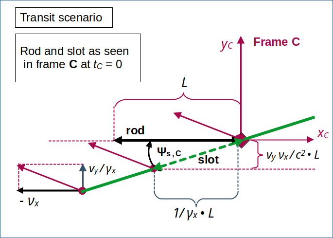
The data above support the following perception of an observer in frame C at tC = 0:

Illustration 2: Perception of the slot passing the rod at tC = 0 in frame C – without collision! The inclination angle Ψs,C and the diagonal movement of the slot guarantee a smooth transit of the rod.
This gives us an idea of how the slot could pass the rod without a collision. The resulting inclination angle Ψs,C helps the slot to pass the rod in diagonal direction: If the resulting diagonal velocity of the slot in frame C moved the left end of the slot to a point to the left of the rod on line yC = 0, then the surrounding plate would not touch the rod. We will look at the encounter and transit of the rod in more detail in the next post.
Just to feel a bit safer, let us find out, when the the left end of the slot reaches the line yC = 0. The time to overcome the vertical distance, which the left end of the slot must pass to reach yC = 0, is given by :
During this time the left end of the slot moves to the following point left on the xC-axis:
This result, indeed, guarantees a collision free passage of the slot.
Conclusion
In this post we have analyzed what an observer co-moving with the rod would experience at tC = 0 in our “transit scenario”. Such an observer would measure the slot not only to move diagonally, but also to have a permanent inclination angle Ψs,C with the xC-axis and the rod. Combining the diagonal movement with the slot’s inclination appears to allow for a collision free meeting of the slot and the rod. The rod just moves through the slot, while the slot passes in diagonal direction.
We will analyze the geometry of the transit process in more detail in the next post.
Special relativity and the rod/slot paradox – X – details of the transit scenario as seen by the rod
For the time being we can safely assume that both an observer in our setup frame Z and an observer in a frame C co-moving with the rod would predict a collision-free transit of the rod through the slot. Obviously, the Lorentz Transformation once again helps to guarantee consistent descriptions by observers located in different inertial frames.
Stay tuned …