My post series about the 2-dimensional rod/slot paradox turns into its last phase. We have learned that there is no paradox regarding two distinct scenarios – defined by different initial conditions:
- Collision scenario: If we in a special reference frame set up initial conditions such that a collision occurs between the rod and the slot-surrounding plate, we will find a collision in reference frames attached to the two moving objects, too.
- Transit scenario: If we set up initial conditions such that the rod can move through the slot at encounter time, we will get the same result in other reference frames, too. In particular in frames attached to the rod and the slot.
You find consistent descriptions of both scenarios in different frames in the previous posts:
- Post I: Special relativity and the rod/slot paradox – I – seeming contradictions between reference frames
- Post II: Special relativity and the rod/slot paradox – II – setup of a collision scenario
- Post III: Special relativity and the rod/slot paradox – III – Lorentz transformation causes inclination angles
- …
- …
- Post IX: Special relativity and the rod/slot paradox – IX – transit scenario and measurements by an observer co-moving with the rod
- Post X: Special relativity and the rod/slot paradox – X – details of the transit scenario as seen by the rod
- Post XI: Special relativity and the rod/slot paradox – XI – Lorentz Transformation between slot and rod for the transit scenario
However, there are still some open questions. In particular, I have not compared the two scenarios directly in some setup-frame. And there other interesting issues.
Regarding the forthcoming posts you should be familiar with the reference frames A, B, C and Z, which I have introduced to mathematically describe observations of different observers. Remember also that reference frame B was attached to the slot and frame C was attached to the rod, which approached the slot on a diagonal path with constant relative velocity. You should also the necessary steps during Lorentz Transformations [LTs] in mind and by what steps we assured simultaneously measured events in the target frame.
Remaining tasks and challenges
Although we have found consistent descriptions of different observers for our two scenarios, we should nevertheless compare these scenarios a bit more directly. Just to get the differences in the initial conditions right in a selected frame. We have, e.g., not yet compared the conditions of the collision scenario with the conditions of the transit scenario in frame Z that we used to define the transit scenario with frame A. Or at least in a closely related frame. A direct comparison requires a LT of collision event data between frame A and Z (or a related frame).
In addition there are also some more aspects of the Lorentz Transformation which deserve a proper discussion. What we for example have not yet looked at are the images of the spatial coordinate axes after a LT to a diagonally moving reference frame. The rod in frame C was aligned with the x-axis there and appeared rotated from the perspective of the diagonally approaching slot. So this makes us suspect that the coordinate axes may appear rotated in some diagonally approaching frame.
If we compare some elementary conditions of the transit scenario in frame Z with the conditions for the collision scenario in A, we must conclude that the relative movement of the origin of a frame like Z would be a diagonal one vs. the origin of A. The reason is simply that Z‘s origin must follow both the horizontal movement of the slot and the vertical movement of the rod in A. So, to be able to compare the collision scenario with the transit scenario we should study diagonally moving frames more closely.
Therefore, another interesting question is how the LT from frame A to a diagonally moving frame as Z can be described by an alternative sequence of two consecutive LTs (more precisely boosts) along two perpendicular axes – so e.g. first along the y-axis (from frame A to frame Z) and afterward along the x-axis of C to frame Z. But there is an alternative sequence, namely from A to B along the common x-axes and then from B to Z along the y-axes. Will the alternative sequence of Lorentz boosts produce different results due to the known non-commutativity of non-collinear boosts? If so, what does this difference mean?
To cover all these points I want to analyze the collision scenario now in a diagonally moving frame W. We will later see that such a frame corresponds indeed in a certain way to the frame Z, which we used for the analysis of the “transit scenario”. This will later allow for a direct comparison of the collision and the slot scenario in a common frame.
We define W as a frame whose origin moves diagonally with respect to frame A (and the standard Cartesian coordinate system there) used to define the collision scenario. We adjust W‘s path such that it moves parallel to the left end of the rod and slot. So, the origin of W will meet the origin of A when the left ends of rod and slot meet there, too. See the illustrations 1 and 2 below.
Our objectives for the forthcoming posts are:
- We want to answer the following two questions: a) What happens to images of the x- and y-axes after a Lorentz Transformation to a diagonally moving target frame W? b) According to which criterion can we reasonably define the orientation of the x-axis of a diagonally moving target system? Do the transformed axes span a Cartesian coordinate system at all?
- We want to find out how the initial conditions of the collision scenario transform from the the setup frame A to a frame W. We should find some profound qualitative difference in comparison to the initial conditions of the transit scenario.
- We have already learned that a Lorentz Transformation along the relative line of motion of our two physical objects is equivalent to a rotation and two boosts along different coordinate axes. On our way to analyze a transformation from A to a diagonally moving frame W we want to investigate what a decision about the order of two alternative boosts along different coordinate axes will mean for the interpretation of the probably differing results. We will learn that in our case the difference corresponds to a choice of the orientation of the Cartesian coordinate system in the target frame. Which may give you a new perspective on the non-commutativity of non-collinear Lorentz boosts (along different axes).
But let us start with introducing a new frame W moving diagonally versus frame A used to analyze the collision scenario. In this post we will try to find out what kind of inclination angles an observer in W observes for the Lorentz-transformed images of the standard xA-axis and the yA-axis of frame A versus the line of relative motion of W vs. A. I.e. we try to find answers for point 1 above.
We use the abbreviations :
CCS : Cartesian coordinate system. LT: Lorentz Transformation.
Introduction of a diagonally moving frame W
The frame W is depicted in the drawing below. In a later post we will see that we can indeed use it to define conditions as in the transit scenario. We assume that W co-moves horizontally with frame B (attached to the slot) versus frame A (velocity component νx in negative x-direction). We also assume that W moves vertically downward in parallel to frame C (attached to the rod) such that the origins of C and W are always on the same height.
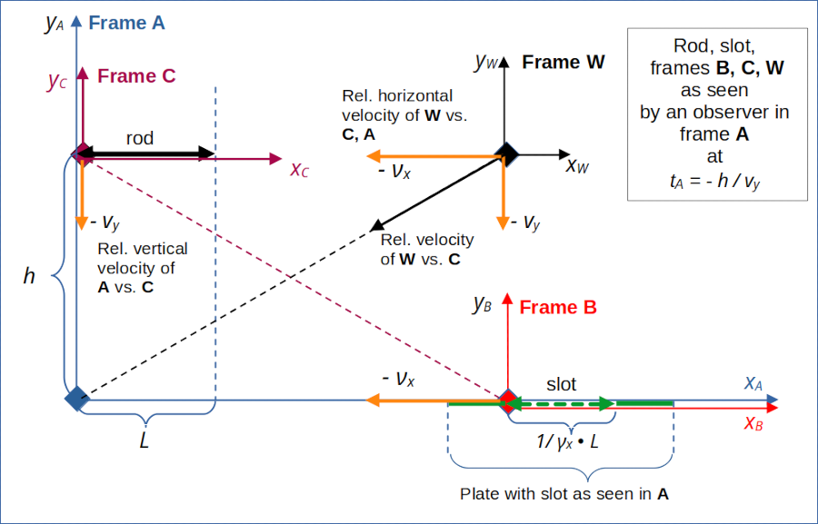
Illustration 1: Introduction of a reference frame W which co-moves horizontally with B and vertically with C. Note that our physical objects – the rod and the slot – move in both frames.
The fact that the rod and the slot are moving in both frames A and W should make us somewhat careful regarding details of the Lorentz Transformation. We can not apply a simple length contraction or its reverse. We have to take into account the 2-dimensional motion of both objects when determining the right events in A that lead to simultaneously perceived events in W.
Relative velocity between frames W and A and some respective formulas
We first gather some information and formulas which can be derived easily. For the presently given Cartesian coordinate system of frame A (see illustration 1) we find that the relative (diagonal) movement of the origin of frame W is defined by the constant components of the following velocity vector vrel,w2a = (vxW, vyW):
Below, we often use the alternative and simpler notation
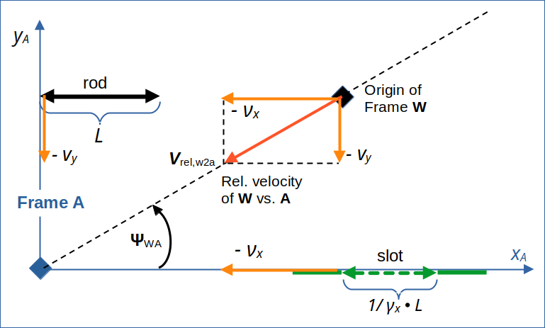
Illustration 2: Relative velocity of the origin of frame W against the origin of frame A as seen in the original coordinate system of A. The vector has two components: –νx and –vy (parallel to the respective axes of A).
This gives us corresponding relativistic β– and γ-factors of
with
The constant velocity components in turn define the angle ΨWA between the line of relative motion and the x-axis in the original coordinate system of A:
Rotated coordinate systems
In this and the following posts we take the freedom to change the spatial coordinate system for a selected reference frame without changing the name of the frame. This may deviate from conventions in some standard books on Special Relativity [SR]. Here, I always keep the origin and motion of a named frame, but allow for a rotation of the 2-dimensional spatial Cartesian coordinate system associated with it.
In particular, we will soon employ coordinate systems of A and W with the x-axes aligned with the line of relative motion between the origins of W and A. In the case of A this coordinate system will be rotated relative to the original coordinate system, which has an x-axis parallel to the slot’s orientation (and the x-axis of frame B). We use a subscript “rel” to refer to the axes of the rotated CCS whose x-axis is aligned with the line of relative motion of the frames..
Choice of a proper x-axis for the diagonally approaching frame W
We work with 2-dimensional Cartesian coordinate systems in this post series. An interesting aspect that comes into our present investigation is the following:
How do we get or define a proper x-axis of a coordinate system for frame W?
The answer is less trivial than you may think. Firstly, this point is a bit different from what we normally do with the orientation of (x,t)-axes and world lines in so called Minkowski-diagrams. Here we refer to the choice of the orientation of a moving 2-dimensional spatial coordinate system with respect to the Cartesian spatial x,y-axes of other reference frames or – much more meaningful – with respect to given physical and measurable quantities in a scenario of moving objects.
In all our previous considerations the target frames B and C had one coordinate axis aligned with one of the axes of the setup frame A. And the physical objects (rod and slot) moved along one of the coordinate axes of A. So, the orientation of the physical object in the target frame B (slot) or C (rod) determined the orientation of the x-axis of either B or C. We did not even have to think about other choices and restricted our efforts to determining the angle of those physically given x-axes relative to line of motion between the reference frames.
But what happens if transformations from A to a diagonally moving target frame W lead to a rotation of both of our physical objects and in addition of the images of the coordinate axes of A? Given our experiences so far we cannot exclude different rotations of our objects physical objects during a transformation from A to W. The resulting angles of the objects with the line of relative motion may also be different from those of the images of the xA– and the yA-axis vs. the line of relative motion.
In the situation depicted above we have assumed a coordinate system of frame W where the xW-axis is displayed as being parallel to the xA-axis of A. This has a well defined meaning in A. But as all points on A‘s xA-axis approach an observer in W with some horizontal and vertical velocity the xA-axis may be perceived in W as rotated against the relative line of motion of the frames’ origins by another angle than in A. If you go through post V again, you will see we found this already before. But at that time we could always cling to the orientation of the physical object attached to the target system. But now, regarding W, it seems that we have an unexpected choice to make.
All in all it feels as if we loose some firm ground now – and as if the choice of the axes of the coordinate system in W is somewhat arbitrary with respect to the initial conditions in A. But, on the other hand, there is always the freedom of choosing the orientation of a 2-dimensional coordinate system in a two dimensional Euclidean space. The special setup of our scenarios only made the choices easier before.
We will sort details out later. For the time being let us do the only reasonable thing SR principles assure us:
The line of motion of the origin of W is physically and mathematically well defined with respect to the origin of A in whatever chosen coordinate system of A. So, in A we can always safely switch to a rotated coordinate system with an xrel,A -axis along the relative line of motion of W. The initial conditions in the unrotated original coordinate system of A precisely define all vector components in the rotated system. And in W the relative line of motion of A defines a proper orientation for an xrel,W -axis there – whatever this may mean
- concerning the possibly different orientations of the rod and the slot in W
- and a maybe different orientation of the LT-image of A‘s xA-axis as perceived in W.
I indicate this approach to cling to the line of relative motion schematically below:
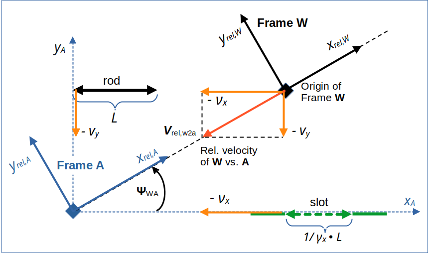
Illustration 3: Rotated coordinate systems of A and W having x-axes aligned with the line of relative motion.
Vector components in the rotated coordinate system with x-axis along the line of relative motion at tA = 0
At time tA = 0, we have the following situation in A:
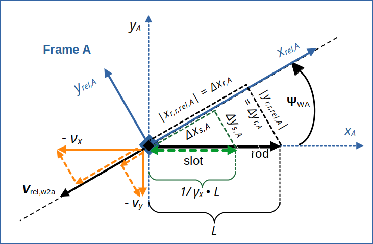
Illustration 4: Conditions in frame A at tA = 0 and components of position vectors and of velocity vectors in the rotated coordinate system aligned with the line of relative motion of W vs. A.
We can now calculate some components of given position vectors by their projection onto the line of relative motion and onto a line vertical to the relative velocity vector. I call the respective distances from the origin of A at time tA = 0:
- Rod: xr,r,rel,A = x-coordinate of rod’s right endpoint with respect to the xrel,A-axis,
- Rod: yr,r,rel,A = y-coordinate of rod’s right endpoint with respect to the yrel,A-axis,
- Slot: xs,r,rel,A = x-coordinate of slot’s right endpoint with respect to the xrel,A-axis,
- Slot: ys,r,rel,A = y-coordinate of slot’s right endpoint with respect to the yrel,A-axis.
We get:
In a similar way we can interpret the velocities of the slot and the rod in A as velocity vectors νx and vy . Then we get the following components of these vectors along and perpendicular to the line of relative motion of W vs. A:
- νx: νx,x,rel,A = component of vector νx of slot’s movement along the xrel,A-axis,
- νx: νx,y,rel,A = component of vector νx of slot’s movement along the yrel,A-axis,
- vy: vy,x,rel,A = component of vector vy of rod’s movement along the yrel,A-axis,
- vy: vy,y,rel,A = component of vector vy of rod’s movement along the yrel,A-axis.
We need these components because we later on have to cover the motion of the rod and the slot in the rotated coordinate systems – both in A and in W. We get:
Transformation of points on the xA-axis to frame W and resulting inclination of the image xA,W of xA in W with respect to the line of relative motion
After having defined some elementary relations above we now try to tackle our first objective: We apply the Lorentz Transformation between A and W to selected points on the standard xA-axis at tA = tW = 0. Applied to all points of xA the LT gives us an image xA,W of the line xA in W. As we deal with linear operations, the analysis of angles requires to look at some selected points on the line, only. One of these points cn be the origin at tW = tW = 0.
The LT will enable us to find the angle between the image xA,W of the xA-axis and the xrel,W -axis in the spatial coordinate system of W. This angle will be different from the respective angle ΨWA found in A.
Let us take a special point on the xA-axis with distance 1 to the origin at tA = 0.
This point does not move in A. (Its world line in a Minkowski diagram would be as straight vertical line.) All the points on the xA-axis do, of course, not move in A. Events fixed to these points do not change their spatial coordinates with time. Neither do their projections onto the line of motion of W to A and projections perpendicular to this line. We name the coordinates of our special point in the rotated CCS of A xxA1,rel,A and yxA1,rel,A:
Projections of the point (1, 0), i.e. the point on the xA-axis with distance “1” to the origin of A:
These are the spatial coordinates of respective events on the world line of the selected point. Let us transform them via a LT along the line of relative motion to respective coordinates in W (with the respect to the rotated 2-dim CCS there). This LT is controlled by the relative velocity vrel,w2a and respective relativistic factors βw2a and γw2a.
I jump over intermediate steps of the LT and use a length contraction of the length interval [0, xxA1,rel,A] (in this case we can use the length contraction due to a non-moving object in A; see previous posts).
The component perpendicular to the line of relative motion does not change during a respective LT :
From this we get the distance LxA1,W of our selected point from the origin as perceived in W:
Not totally unexpected! Can you guess why?
This tells us that in W the angle ΨxA,W between the image xA,W of the original xA-axis and the line of relative motion is given by:
Transformation of points on the yA-axis to frame W and resulting inclination of the image of yA in W with respect to the line of relative motion
When we perform similar calculations for a point with distance 1 on the yA-axis we get:
Calling
- the angle between the yA-axis and the line of relative motion Ψy,A in A
- and between the image yA,W of the yA-axis and the line of relative motion ΨyA,W in W,
we get:
All in all we find that for our (diagonal) relative motion of W versus A the angle of the LT-images of the original coordinate axes of A with line of motion in W are bigger than the angles of the original axes with the line of relative motion in A. And the images of the axes have no angle of 90° versus each other in W, but a larger angle ΨxyA,W.
Angle ΨxyA,W between the images of the coordinate axes of A in W:
Funny, isn’t it?
Note that while our frame W was chosen with respect to physical conditions of our scenario this general qualitative result would hold for other diagonally approaching frames, too.
I have schematically depicted differences in the angles below. The change in angles is exaggerated.
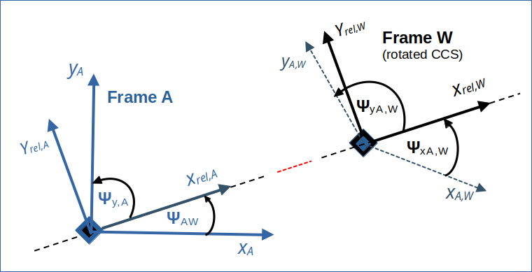
Illustration 5: Schematic illustration of angles in A and the widening of the angles of the images xA,W and yA,W of the axes xA and yA by the the LT from A to W. The change of angles depends on the velocities νx and vy. The differences in the angles are exaggerated.
So, the images of the xA– and the yA-axes form no Cartesian coordinate system in W! This makes them no good choice for the yet to choose axes xW and yW to cover our 2-dimensional Euclidean space in W.
What can we do? Well, we could choose the image xA,W of the xA-axis as our xW-axis and define a yW -axis perpendicular to it. This is an interesting approach. But, in may opinion, a better and physically more solid approach is the following:
- Calculate the inclination of the slot (or the rod) in W vs. the xrel,W-axis of the rotated coordinate system of W via the simple LT-boost defined by vrel,w2a.
- Define the xW -axis as aligned with the orientation of the slot (or the rod) in W.
This does not exclude the possibility that one of the physical objects may have the same orientation as the image xA,W at tW = 0 in W. We might think of the slot. But after a full LT along the line of relative motion we would have proved it …
Conclusion
In this post we have changed our perspective on the rod/slot paradox once again. We introduced a diagonally moving frame W. We hope that we can later use it to define a transit scenario there for a direct comparison of the initial conditions of both scenarios in a common reference frame.
We have started to analyze the collision scenario in W to understand the consequences of the LT to a diagonally moving frame a bit better. A first new insight was that the images of the axes of frame A get different angles in W versus the relative line of motion of W vs. A than in frame A. The images of the axes are not perpendicular to each other. Their relative angle is widened by the LT to a diagonally approaching frame.
We may therefore be forced to determine the orientation of one of the physical objects (rod, slot) in W and maybe define a suitable xW-axis aligned with the selected object. And define a related vertical yW-axis accordingly. Another very reasonable approach would be to first work with rotated coordinate systems in A and in W which are aligned with the line of relative motion of the origin’s of both frames versus each other.
This is the topic of the next post.
Stay tuned …