This post series is a about a paradox based on the length contraction effect in Einstein’s Special Theory of Relativity [STR]. In the previous first post I have presented a simple version of the so called “rod/slot [RS] paradox“. In this 2nd post I will in detail define a setup for a “collision scenario” between a rod (moving downward in vertical direction) and a plate with a slot moving horizontally at a level y = 0. The conditions and details of the setup will provide the basis for a later deep dive into the RS-paradox – guided by the Lorentz transformation and respective mathematics.
Previous post:
- Post I: Special relativity and the rod/slot paradox – I – seeming contradictions between reference frames
Two reference frames and rod/slot movements for a collision
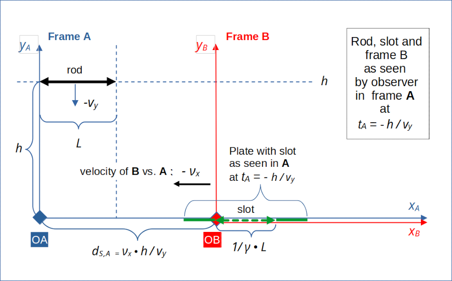
The graphics below shows (x,y)-coordinate systems of two reference frames, frame A and frame B, which move with a constant horizontal velocity νx against each other. As defined in the 1st post reference frames represent physical inertial systems throughout this post series. The origins of the coordinate systems are located on the horizontal line of relative motion of the two frames against each other. We will in general indicate in which frame values of certain quantities (as e.g. event coordinates or velocity components) have been measured by respective subscripts “A” and “B”.
The coordinate systems are oriented such that both the xA-axis and the xB-axes are aligned with the constant vector ν of the frames’ relative velocity. The y-axes are perpendicular to the x-axes. I.e., the yA-axes is parallel to the yB-axis.
The vector of the frames’ relative velocity has a component in x-direction, only: Seen from frame A, frame B moves horizontally with a negative constant velocity –νx. There is no relative vertical motion between our frames A and B.

Illustration 1: Vertically moving rod and horizontally moving slot seen from frame A at time tA = –h/vy
Frame A will be used as a standard setup frame for the collision scenario in many of the forthcoming posts. But we will see that we need other setup frames, too, for the proper definition of a very different “transit scenario“, in which the rod will move unharmed through the slot. See posts VIII to XI for the discussion of a transit scenario.
Note and warning: We will often use the words “horizontal” and “vertical” to describe the movement of the rod/slot objects in certain reference frames. This, of course, makes only sense with respect to a chosen Cartesian coordinate system. In most cases we will use coordinate systems for our frames with an x-axis oriented along the orientation of one of our elongated objects. Presently, we use an x-axis aligned with the slot and parallel to the rod. However, we will later see that the choice of a proper coordinate system may become a subtle problem, because the Lorentz Transformation in two dimensions can induce relativistic rotation effects and inclination angles between the objects.
Vertically moving rod in frame A
In frame A a long thin cylindrical rod is positioned such that its the rotational symmetry axis is parallel to the xA-axis. The extensions of the rod in y-direction (as well as in z- direction) shall be infinitesimally small. We indicate quantities referring to the rod by a sub-script “r“.
The rod moves vertically downwards in frame A with a constant velocity of vr,y,A in (negative) y-direction. The rod is force-free. We will name the absolute value of this velocity in the future vy – always being aware of the fact that this value was defined in a special frame, namely frame A. This is important as the vertical velocity of the rod will have different values in other reference frames.
We start watching at a time tA = tstart,A when the rod just passes a height yA = h in frame A.
The rod shall reach the base level yA = 0 at a time tA = 0. All initial conditions of our scenario are therefore given at a point in time tA = – h/vy in frame A:
Horizontally oriented plate with slot at rest in frame B
In frame B we have a very thin impenetrable plate with a slot in it – oriented in parallel to the xB-axis and at level yB = yA = 0. We indicate quantities referring to the slot by a sub-script “s“.
The slot’s left end is located at xB = 0, i.e. it coincides with the origin of B‘s coordinate system. The plate and the slot do not move in frame B:
Seen from frame A, however, the plate and the slot are moving horizontally in negative x-direction with a speed of –νx versus A‘s origin.
Below the plate is nothing. So, if the rod could pass the slot’s opening under certain conditions, the rod would just move on in negative y-direction.
Timing conditions
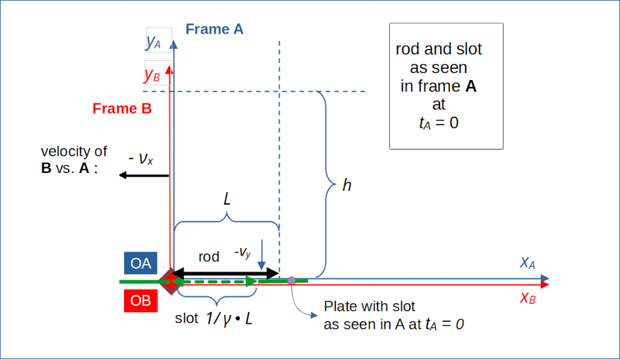
We define the timing of the slot’s movement relative to A such that the left end of the slot (and thus also the origin of frame B) will coincide with the left end of the rod in frame A at xA = 0 at tA = 0. We have prepared clocks in frame B such that this event also has a time coordinate of tB = 0 there. We indicate left ends (of the rod or slot) by an additional sub-index “l “, right ends by an additional sub-index “r“:
This imposes a condition on the distance ds,A of the left end of the slot from the origin of A as seen from an observer at tA = tstart,A in A:

Illustration 2: The rod, the plate with the slot and frame B at tA = tB = 0 as seen from frame A
Orientation of the rod and the slot
Please note that the orientation of the rod and the slot in the illustration refer to frame A, only! The drawing does not indicate anything regarding the orientation of the rod relative to the slot as seen or measured in frame B. More precisely:
Frame A: Seen and measured from an observer located at a fixed point in frame A, the slot is always oriented horizontally, i.e. parallel to the rod and parallel to the xA-axis in our collision scenario. In frame A both of the slot’s ends always have a y-coordinate yA = 0. In frame A both ends of the rod always reside at the same y-coordinate during the fall of the rod.
These appear to be trivial statements. But we will later see that these point of our setup are really worth to be emphasized. They mark important initial conditions.
Proper lengths of rod and slot / length contraction of the slot
Extensions of the rod and the slot vertical to the x-axis are basically irrelevant in so far as they would not hinder a passage of the rod through the slot. We simply ignore them. Our thin, but lengthy rod has a proper length L. The slot in the plate also has a proper length L plus an infinitesimally small extend ε to ensure that the rod could in principal move through the slot.
We ignore the infinitesimal excess of the slot in x-direction in forthcoming calculations.
We know from a basic course in special relativity [SR] that the length contraction effect will give us a diminished slot length in A (compared to what observers would measure in frame B, where the slot is at rest). Remember that the proper length of an object is measured with the object being at rest in some frame. Remember also that a length measurement process is defined such that the length of an object should be determined by observers measuring the spatial coordinates of the object’s ends at the same point in time in a given reference frame. This condition is essential for the length contraction.
Due to the length contraction effect we will find that the length of the slot Lslot,A as seen in frame A at any point in time tA is:
c is the velocity of light in vacuum. This means:
Diagonal movement of the rod versus the slot in frame A
Seen from the slot, the rod approaches diagonally with two constant components of its velocity. We will later need to apply the Lorentz transformation to determine the orthogonal component of the relative velocity between the rod and the slot objects in frame A and frame B.
Additional remarks regarding the scenario
- No forces or accelerations are at work in our scenario.
- Neither the x-axis of frame A, nor the x-axis of frame B are oriented along the line of relative movement between the left end of the rod and the left end of the slot.
- According to the Lorentz-transformation y-coordinates of events remain constant between inertial frames moving relative to each other along the x-axis.
- Seen from the slot the rod appears to approach at some diagonal line. To determine the values of the objects’ velocity components in x- and y-direction in frame B, we will have to apply the Lorentz-transformation to the defined object velocities in frame A.
A predetermined crash of the rod at the slot’s right border
From illustrations 1 and 2 you can derive a predetermined development of the rod/slot encounter in our scenario:
In frame A the conditions are defined such that the rod has no chance to pass the slot vertically without an accident and without touching the plate. In A both the right and the left end of the rod will reach the plate and the slot at the same time tcoll = tA = 0 :
We saw that the slot’s length in A at tA = 0 is measured to be:
Hence, in A the rod’s length L will be to big for the slot. We therefore expect the rod to crash at our plate at a an xA-coordinate
Note that the length contraction does not describe an apparent length. It gives us the real length of the moving slot measured in A.
The paradox seems to be that length contraction in frame B will shorten the slot by a factor \( 1 / \gamma \lt 1\). Therefore in frame B one is tempted to assume that the rod falls through the slot there. We will see in the next posts that this assumption is false.
Conclusion
We have set up a scenario with a rod moving vertically downward in a special reference frame A. In this frame we also considered a horizontally moving plate, with a slot, along a zero y-level. The timing was such that the rod’s left end would meet the slot’s left end when it reaches yA = 0. Rod and slot have the same proper length. Therefore, due to the length contraction effect, we expect a collision of the rod’s right outer part with the plate.
In the next post
Special relativity and the rod/slot paradox – III – Lorentz transformation causes inclination angles
we will apply the Lorentz transformation to the coordinates of certain key events occurring in our collision scenario. This will show that in a frame B (attached to the slot) the rod will not be oriented in parallel to the slot.
Stay tuned …