We continue with our study of the rod/slot paradox in the Special Theory of Relativity. We consider 2-dimensional scenarios in which the rod approaches the slot along a diagonal track. Rod and slot have the same proper length. We are interested in the predictions of observers either co-moving with the rod or with the slot. Such observers could potentially come to conflicting conclusions about the rod’s encounter with the slot (and a surrounding impenetrable plate). At least if one naively argues with the relativistic “length contraction effect”, only.
So far we have discussed a 2-dimensional “collision scenario“, which we defined in a special reference frame A. There, a rod meets a length-contracted slot (of the same proper length as the slot). However, due to the inverse Lorentz Transformation equations, we expected a length contraction of the rod in an inertial frame B co-moving with the slot. Nevertheless, we found that also an observer in frame B would predict a collision of the rod with the plate due to a relativistic rotation effect. For details see the previous posts and a summary below.
Does our derived rotation have a name? Yes, it has – it is a variant of the so called “Thomas-Wigner rotation“. Advanced students may read articles on the Internet about it. I will come back to this point in future posts – after we have gotten more familiar with rotations occurring in the perception of different observers for moving objects due to the Lorentz Transformation.
In the present post we will instead start with a description of our collision scenario from the perspective of the rod. We introduce a related reference frame C, which we attach to the rod. Of course, a physical system, in which the rod is at rest, is an inertial system, too. So, we can first try a Lorentz Transformation [LT] between our frame A and frame C. However, our ultimate goal for the forthcoming posts is a (direct) Lorentz Transformation [LT] form frame B to frame C – and reversely from C to B. Due to the diagonal motion in the spatial coordinates systems used so far, this requires a careful preparation and a series of intermediate mathematical steps. The post provides us with some fundamental relations.
Previous posts:
- Post I: Special relativity and the rod/slot paradox – I – seeming contradictions between reference frames
- Post II: Special relativity and the rod/slot paradox – II – setup of a collision scenario
- Post III: Special relativity and the rod/slot paradox – III – Lorentz transformation causes inclination angles
- Post IV: Special relativity and the rod/slot paradox – IV – consequences of an inclination angle in the slot’s frame
Work plan of this post
1) We start with a repetition of our initial conditions. I will discuss why it is of major interest to take into account the rod’s perspective. 2) We will then apply a LT between frame A and frame C. This will give us some reference values and the relative orientation of the rod vs. the slot in C. 3) We then evaluate the absolute value of the relative velocity between the rod and the slot both for observers in B and in C. We expect the results to be equal, because otherwise the formulas of a direct LT between B and C (and its reverse transformation) would loose their dependence on unambiguous and unique β– and γ-factors. 4) Afterward we will determine the orientation of the relative velocity vector of the rod versus the slot in B – and vice versa the orientation of the relative velocity vector of the slot s. the rod in frame C.
We will find that the LTs between the different reference frames force us to introduce further inclination angles to fully cover our collision scenario. In particular the angle between the vector of relative velocity and the x-axes of the frames attached to the slot (frame B) and to the rod (frame C) will be found to be different. This may come as a surprise to you – but it again marks a subtle and noteworthy difference of kinematics in Special Relativity compared to Newtonian physics.
Why is the perspective of the rod important? And why should we also try a Lorentz Transformation between reference frames attached to the rod and the slot?
Einstein’s Special Theory Relativity discusses the description of phenomena by observers in different inertial frames moving with constant velocities versus one another. In our 2-dimnsional scenario we can describe the movement of the rod and the slot as seen from three major frames of reference:
- the setup frame A (neither co-moving with the rod nor the slot),
- a frame B co-moving with the slot
- and a frame C co-moving with the rod.
Our special setup in frame A (neither attached to the rod nor to the slot) ensures a collision between the rod and an impenetrable plate around the slot. For details and naming conventions see the previous posts and the schematic figure below.
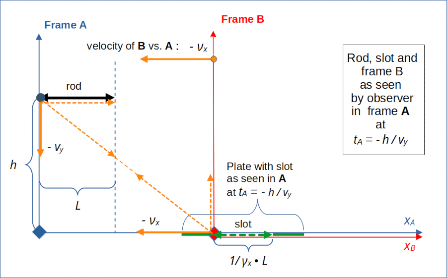
Illustration 1: Setup of the collision scenario as seen in frame A. The relative diagonal motion of the rod versus the slot ensures that the left ends of the rod and slot meet at collision time tA = tB = 0. Length contraction affects the slot and causes a collision of the rod with an assumed plate around the slot.
The rod moves vertically downward along the yA-axis in frame A. The slot instead moves horizontally along the xA-axis vs. the origin of frame A. The dotted vectors illustrate the relative motion of the rod vs. the slot against each other schematically. As we will see soon, observers co-moving with the rod and the slot will measure different velocity components than the displayed ones.
Frame B is attached to the slot and obviously co-moves with the slot. Frame A, however, is not co-moving with the rod. While we have already discussed perceptions of the rod/slot encounter by observers in A and B, we have not yet mathematically derived what an observer moving with the rod in frame C would see. This is kind of a deficit in our argumentation against a paradox because of the following reasons:
- Typical presentations of the rod/slot paradox refer to the rod’s perspective in contrast to the slot’s perspective. So, we should cover both perspectives.
- All observers (here in frames A, B, C) should come to the same physical conclusions about the outcome of whatever scenario for the rod/slot encounter.
- What physically counts is not the choice of a reference frame, but the relative motion of the rod versus the slot and vice versa – and the results of a direct LT between the respective frames B and C (and of its reverse transformation) must be consistent with results derived by other LTs. Only with positive results of such a LT we could claim to have achieved a fully consistent picture.
A full consistency between the perspectives of different observers would resolve any potential paradox to a large degree.
Complications regarding a LT between frames B and C
Up to now, the familiar simple form of the Lorentz Transformation as given in the 3rd post could easily be applied, as we could refer to the relative motion of our frames A and B along their aligned x-axes. Another simplifying aspect was that the slot’s orientation coincided with that of the x-axes.
Using a Lorentz Transformation along the (diagonal) line of relative motion between the rod and the slot is more complicated. The reason is that we need the spatial coordinates of key events as measured in coordinate systems who have x-axes oriented along this line of relative motion. Respective Cartesian systems would be rotated relative to our presently uses coordinates systems for B and C. To cover this point mathematically we must know the angle(s) between the vector of relative velocity and the present x-axes of frames B and C. Afterwards we can calculate the required event coordinates in the rotated coordinate systems with the help of projections and some trigonometry.
There are two points we have to care about:
- We have to ask ourselves whether observers attached to the slot on the one hand and to the rod on the other hand measure the same or different inclination angles of the relative velocity vector against their own x-axes. Despite the fact that these angles appear to be the same in frame A, this cannot safely be assumed for B and C.
- As the slot moves diagonally relative to the rod, we cannot a priori exclude an inclination angle of the slot against the rod from the perspective of an observer attached to the rod.
The reason why we have to take the 1st point seriously is that the velocity components of the moving objects may transform differently from A to B than from A to C due to different time dilation effects! Point 2 is founded in our experience with the diagonally approaching rod as seen in frame B.
Lorentz transformation from frame A to a frame “C” fixed to the rod
Let us introduce a new reference frame C, which fully co-moves with the rod. As the rod moves with constant velocity downwards in A, frame C is an inertial system: We can apply a LT to transform coordinates for events measured in A to respective coordinates measured in C.
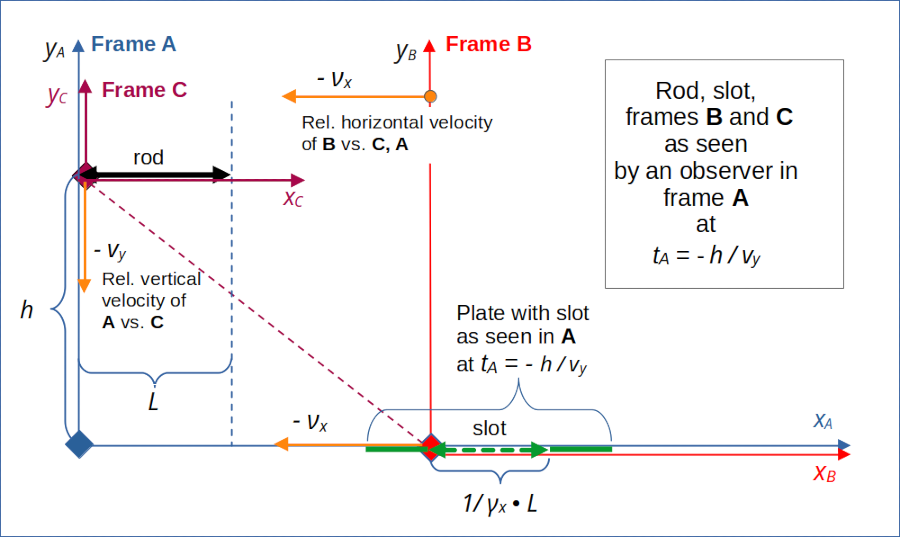
In one of the last posts we performed a Lorentz transformation between frames A and B. Now, you can do the same for frames A and C which also move with a constant relative velocity against each other. For the general formulas of the Lorentz transformation see the 3rd post. But watch out! In the present case we have a relative velocity between C and A along the y-axis! So, to apply our general LT formulas correctly, you have to reinterpret and adjust the indices there.
The good thing about frame C is that it just moves vertically downwards relative to the origin of frame A. So we have a simple relative velocity vector vrel,CA between these frames. In frame A it is given by:
This relative velocity –vy is central for the Lorentz transformation of event coordinates and of velocities (of moving objects) from A to C. The related β- and γ-factors are:
With this information we apply the (adjusted) Lorentz Transformation to the space and time coordinates of the same special events in frame A which we analyzed in previous posts. I leave the details to the reader. Note that for our specific scenario the xA-coordinates of events in A remain identical with respective xC-coordinates as vectors in x-direction are perpendicular to the relative velocity between C and A.
What about the velocity vslot,C of the slot in frame C? The velocity of the slot vs. the origin of A has, of course, only one non-zero component, namely –νx . This velocity component is perpendicular to the relative velocity vrel,CA in frame A and transforms to have two components in C:
In C the slot moves diagonally upwards (to the left).
Predictions of observers in frame C
The LT between A and C gives us the same x-coordinate values for the rod’s and the slot’s ends in C as they are measured in A – at any point in time. In addition the LT won’t change the simultaneity of respective events. We therefore come to the conclusion that also from the perspective of C, the slot is oriented in parallel to the rod.
And as there is no further length contraction involved, neither of the rod or the slot in comparison to what is given in A, the slot’s length is too small for the rod’s length in C, too:
This is something a later direct Lorentz Transformations between frame B and frame C should definitely reproduce.
All in all frames A and C are very similar regarding the initial conditions which predetermine the collision of the rod with the plate around the slot. We could actually have started with frame C to set the collision scenario up. This scenario is special in C in so far as it prescribes a parallel orientation of the slot and the rod, there.
Side remark: Some readers who have swallowed the idea that diagonal movements may lead to some rotational effect may get nervous, now. From the perspective of C the slot approaches diagonally. So, what would cancel a potential relativistic rotation of the slot vs. the rod during a LT from B to C? Well, you should not forget that in B there actually is an angle between the rod and the slot. So, a LT from B to C would at least compensate for this angle by some rotational effect.
To get better control we now have to find the relative velocity vector between the slot and the rod, the absolute value of the vector’s length (norm) and its orientation versus the x-axes, both in frame B and frame C.
Relative velocity between the rod and the slot
Let us look again at the initial conditions of our collision scenario as set up in our special frame A. You may think that a standard observer in A can determine the orientation of the relative velocity of the left end of the rod vs. the left end of the slot in a frame-independent way. But this is wrong. The reason lies in a difference between the time dilation effect between frames A and B compared to the time dilation measured between A and C.
Relative velocity of the rod vs. the slot as perceived by the slot
While the horizontal velocity of the rod in the slot’s frame B is given by the relative frame velocity νx, the rod’s vertical velocity in frame B is reduced due to time dilation (with respect to frame A)
Thus, we get a constant velocity vector vrod,B for the rod’s movement vs. the slot in B:
This and other aspects of the Lorentz transformation between A and B gave us the following perception of the relative motion of the rod towards the slot as seen in B :
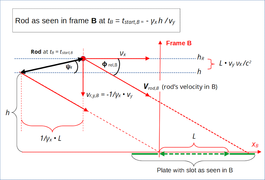
Illustration 2: Relative velocity of the rod as seen by the slot (frame B)
In the drawing I have marked an inclination angle Φrel,B of the velocity vector vrod,B with the xB-axis and thus also with the slot:
This angle is negative due to the rod’s diagonal movement downwards. An interesting quantity is the length (or Euclidean norm) of the vector vrod,B :
The velocity vrod,B is identical to the relative velocity vrel,CB of frame C vs. frame B:
As this velocity vector is constant, frame C is an inertial system from the perspective of B.
The next drawing shows more or less the same as illustration 2, but more compact and with focus on the relative movement of frame C vs. frame B. Note that it is only a schematic drawing; scales and velocity components were chosen relatively freely:
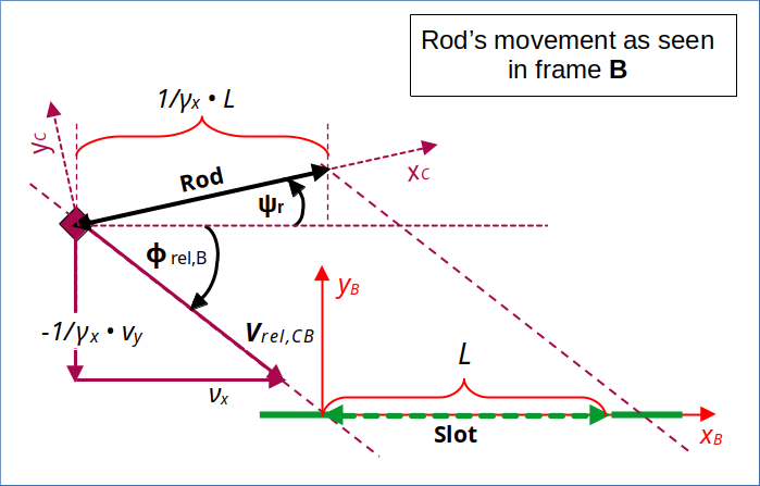
Illustration 3: Relative velocity of rod and frame C vs. the slot – as seen by an observer in frame B attached to the slot
I have indicated that the coordinate axes of frame C may appear rotated by some angle(s) in frame B. That we find an alignment of the perceived xC-axis with the rod’s orientation is, by now, just a plausible assumption. Note that the inclination of the vector for the relative velocity of C vs. B is determined by respective velocity components measured in B. We have to pick them from the Lorentz Transformation that couples setup data in frame A to coordinates determined by an observer with synchronized clocks in frame B.
Relative velocity of the slot vs. the rod as perceived by the rod
Let us now see what our LT from A to C predicts for the measurement of the relative velocity vslot,C of the slot vs. the rod in frame C. Illustration 4 shows what we might expect:
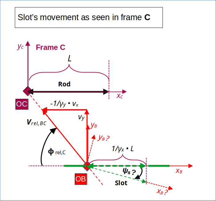
Illustration 4: Relative velocity of the slot and frame B vs. the origin of frame C and thus also vs. the rod.
To be careful and also to cover more general cases than ours, I have indicated that we might find an inclination angle ΨS between the slot and the rod. Although we, for our special collision setup, expect that this angle is ΨS = 0. (Hopefully, also an LT from B to C will give us this result …).
Are there any expectations regarding the value of the relative velocity vrel,BC = vslot,C? As the symmetry of the two possible LTs between two inertial systems (with their x-coordinate axes aligned with the relative velocity vector) depend on the absolute value of the relative velocity, only, we expect that at least this value is identical in B and C, i.e. ||vrel,BC|| = ||vrel,CB|| .
Actually, we have determined the slot’s velocity in C, already above and get
That vrel,BC is identical to vrel,CB can be seen by some simple algebra:
So, indeed,
The reader can easily derive another interesting key equation for the gamma-factor related to this relative velocity between the rod and the slot:
with
Angles of the relative velocity between the rod and the slot vs. the x-axes of frames B and C
The components of the velocities transformed from frame A to B and to C, determine the inclination angle of the relative velocity vectors in each of the frames. And, in contrast to the absolute value of the relative velocity these angles are not identical:
whereas
This gives us
Regarding cos- and sin-values we find:
These are very useful relations which we will apply during a LT from frame B to C in the next post.
Conclusion
In this post we have applied a Lorentz Transformation between frame A and a new frame C attached to the rod. From the results we expect that we get a collision in frame C, too.
If all our previous considerations were correct, we must, therefore, reproduce a consistent description in frame C also by applying a Lorentz Transformation between our frames B and C.
So, far we have understood that the absolute value of the relative velocity between the slot and the rod is the same in B and C. However, the orientation of the relative velocity vectors as determined in B and C show different inclination angles versus the respective x-axes. The reason lies in different transformations of the velocity components from frame A to target frames B and C.
By having determined the angles and relation for the gamma-factor related to the relative velocity between rod and slot, we have laid the base for further work. In the next post
we will perform the Lorentz Transformation between the frames B and C.