In the course of the first two posts of this series we have set up a collision scenario to study the the rod/slot paradox in the Special Theory of Relativity [STR]: A rod falls vertically in a reference frame A and eventually meets a horizontally moving plate with a slot. We have also introduced a frame B co-moving with the slot. The 3rd post has provided us with some results of the Lorentz Transformation applied to key event coordinates measured in A. In this 4th post we will look at details of the rod’s movement towards the slot as seen by an observer in frame B. The already derived inclination angle of the rod against the slot and the rod’s diagonal movement ensure a collision in B. Despite the facts that the rod and the slot have the same proper length and that the relativistic length contraction affects the rod in frame B. We will also find an interesting sequence of xB-coordinates for key points on the rod and respective events.
Previous posts:
- Post I: Special relativity and the rod/slot paradox – I – seeming contradictions between reference frames
- Post II: Special relativity and the rod/slot paradox – II – setup of a collision scenario
- Post III: Special relativity and the rod/slot paradox – III – Lorentz transformation causes inclination angles
Just a hint to avoid misunderstandings: We could, of course, have chosen other initial conditions such that the rod would move through the slot without any collision. Such a collision-free “transit scenario” will be the topic of later posts in this series.
Previous results of the Lorentz transformation for events in our “collision scenario”
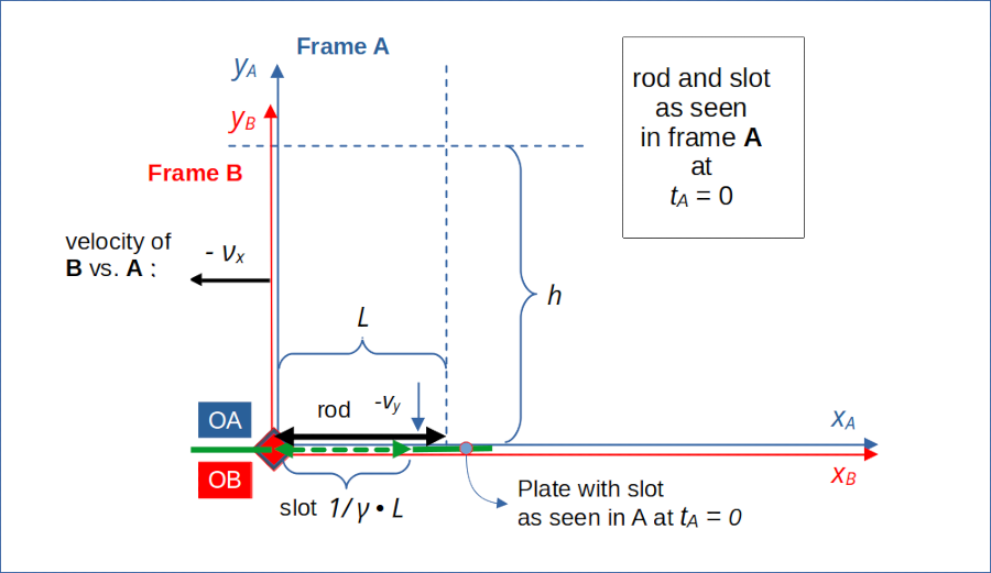
For a summary of settings for our present “collision scenario”, basic coordinates, quantities and respective notations see the previous posts and illustrations 1 and 2. The schematic drawing below depicts the situation of the rod touching the slot at tA = 0 and yA = 0, after a phase of the rod’s vertical downward movement in A with a velocity –vy.

Illustration 1: Vertically falling rod in a horizontally co-moving frame A at tA = 0 touching the line yA = 0
Initial conditions were such that the left end of the rod after having moved from a height yA = h to yA = 0 also touches the left end of a slot. The slot moves with horizontal velocity –νx at yA = yB = 0 along the xA-axis.
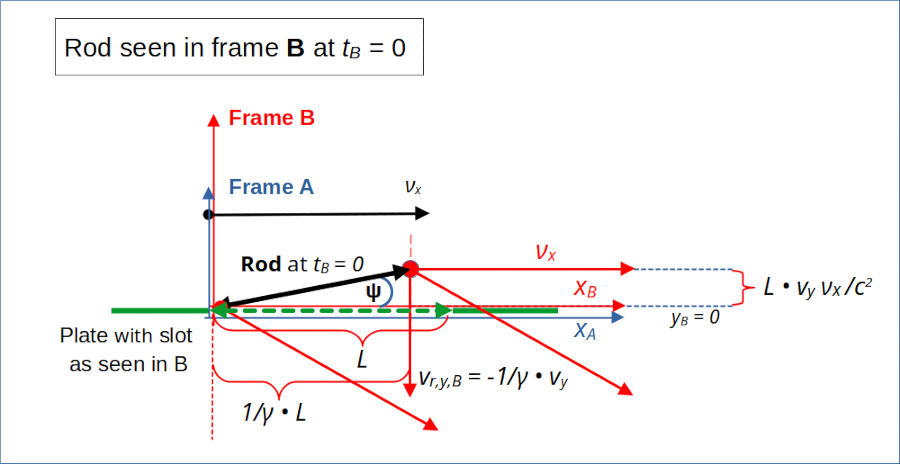
A major result of the Lorentz transformation in the previous 3rd post was that the rod as seen from frame B (where the plate with the slot is at rest) shows an inclination angle Ψ with the x-axis. This is depicted in the next drawing at tB = 0:

Illustration 2: Inclination angle of the rod with the x-axis in frame A at tA = 0
You also see that the vertical velocity of the rod in B is vr,y,B = 1/γ • vy. The overall movement of the rod vs. the slot is a diagonal one. For the time being we use the standard factors of STR:
The appearance of the inclination angle is a result of the so called relativistic “Thomas-Wigner rotation” for extended objects moving in two dimensions vs. each other.
A detailed view at the expected collision in frame B
The results of the 3rd post have already indicated that the rod’s right end might crash against the plate beyond the right end of the slot. We shall look at this now in more detail. I first repeat some results for the space and time coordinates of events E1 and E2 at which the rod’s left and right ends pass the line yB = 0 (= yA) in B.
In our shorter event notation:
The differences in space and time in B are given by :
Obviously, E2 and E1 do not happen at the same time in B. The rod’ right end passes the line yB = 0 later than the rod’s left end – and at a bigger xB-coordinate than L !
In contrast to this we found that the time coordinate of an event E2R (related to the rod’s right end) transformed to tB = 0 in B:
The yA-coordinate of E2R transforms into an equal yB – coordinate :
Interpretation: Collision !
Note the important result for the right end of the rod when it passes passing the line yB = 0 (event E2). With xs,r,B meaning the right end of the slot in frame B:
We have already checked this result in the 3rd post for consistency with velocity components in B and the respective time difference to move down to yB = 0 and to the right on the xB–axis.
So, we have a clear indication now that the rod’s right end will not pass the slot’s right end xs,r,B = L in frame B, but instead crash against the plate! Somewhat later than tB = 0 (see below): The rod’s right end eventually hits the plate at the time of event E2.
Frame B: A nice sequence of lengths and events
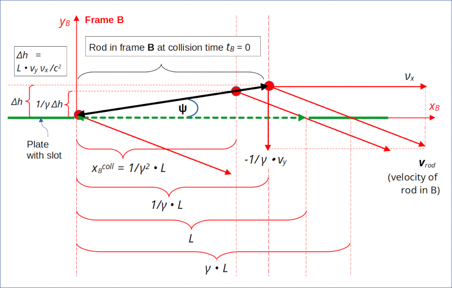
The following illustration reveals some more details of the rod’s movement ahead of the collision as registered by an observer in frame B. We get a nice sequence of xB-intervals for some key points on the rod and respective events :

Illustration 3: Rod as seen in frame B close to touchdown. The rod shows an inclination angle with the xB-axis and the slot. Velocity vectors and coordinates for the rod’s right edge crossing line yB = 0 clearly indicate a collision.
We recognize our angle Ψ again, for which we had found the following equation in the previous 3rd post:
We understand that due to this inclination and the rod’s diagonal velocity, the rod’s right end must move longer to the right than the location of the slot’s right end to reach a y-level of yB = 0.
The diagonally oriented velocity vector of the rod vrod,B has the components:
As we have already seen in a previous post the timing is such that the rod’s right end indeed moves horizontally from xB = 1/γ • L to xB = γ • L between the events E2R and E2:
This is exactly what we need!
Movement of the special point on the rod which collides with the slot’s right end
From the setup of our “collision scenario” we already know in which part of the rod we expect the collision with the plate to happen: In frame A the leftmost collision point on the rod has the same xA-coordinate as the right end of the (length contracted) slot:
We apply the Lorentz transformation to get a corresponding coordinates In frame B:
As expected! The respective point in time, at which the collision for his special point on the rod occurs, lies between tB|E2R and tB|E2 :
Coordinates of the leftmost collision point in frame B at tB = 0
Just for fun and as a consistency check, let us derive the xB-coordinate of the rod’s particular point, which collides with the plate at the slots right end, from the given velocity components and tBcoll.
As we have xBcoll and tBcoll in B, we just can get the xB-coordinate of the collision point on the rod relative to the rod’s left end by calculating the distance this point must have moved to the right since E1, i.e. in the time interval Δtcoll = tBcoll – tB|E1 :
From this we can easily get the height of this point at the time of event E1 in frame B:
This is consistent with the time our particular point needs to move vertically down to yA = 0 :
So, we have an event E0C with coordinates for the leftmost collision point of the rod at tB = 0:
We can back-transform the event E0C for the rod’s leftmost collision point at tB = 0 from frame B to frame A:
We get the expected x-coordinate. But we find a backwards shifted time coordinate and thus a different y-coordinate, which in turn fits the vertical movement with velocity -vy in A for reaching the y-level yA = 0.
Collision as a series of events in frame B
The collision unfolds in frame B as a series of events:
- Firstly, the left end of the rod crosses the line yA = 0 unhindered with diagonal velocity vrod,B.
- Secondly, the point with xB-coordinate 1/γ2 • L (at tB = 0) reaches the slot’s right end at xB = L at time tB = νx/c2 L.
- Thirdly (and somewhat theoretically) the rod’s right end may collide with reach the plate at xB = γ • L at time tB = γ • νx/c2 L.
Hmm, wait a second. We have shown that a collision will occur in frame B, too.
BUT:
If a special point on the rod touches the plate first due to the rod’s diagonal movement, would this not have direct consequences for the rod’s outer right part? A completely stiff rod (which is not realistic) may actually turn into an anti-clockwise rotation movement around the collision point – and the rod’s right end would never reach the y-level yB = 0. In contradiction to our collision setup in frame A.
Following this line of thought goes beyond the intentions of this series. We may get lost in aspects of a relativistic definition of stiffness and the respective propagation of sound waves through the solid grid of the rod at the atomic level. Let us not go there and postpone this topic to other posts.
The concerned reader may instead have a second look at the collision setup in frame A – and allow for an infinitesimal inclination of the rod there, too. Then the collision at the slot’s right end would also introduce an anti-clockwise rotational movement of the rod around the collision point in A. I hope this helps a bit to trust in the consistency of the observations in A and B.
The length of the rod in frame B
Just for the sake of completeness let us calculate the length of the rod in frame B. We use Pythagoras to get:
This gives us:
So, in the slot’s frame the total length of the rod is actually shorter than L. But due to its inclination and its diagonal movement it nevertheless collides with the plate.
So, all in all, an observer in frame A has a different perception of the rod and measures different properties of the rod than an observer in the slot’s frame B. An observer in frame B, co-moving with the slot, measures an inclination angle of the rod vs. the slot and a shorter length of the rod than its proper length. Nevertheless, due to the diagonal motion of the rod vs. the slot, the rod’s right end is seen to collide with the plate around the slot.
Conclusion
In this post we have shown the following: The Lorentz transformation for events in our rod-slot-“collision scenario” leads to a consistent prediction of a collision in both (!) of our selected frames
- in frame A in which the rod falls vertically.
- in frame B, in which the slot is at rest and which moves horizontally versus frame A.
If the rod is doomed to collide with the plate (around the slot) in frame A, then the Lorentz transformation inevitably leads to a collision with the plate in frame B, too. So, from all we have done so far, we may get some hope that there is no paradox for the collision scenario in the end!
What may still lead to some confusion concerning our collision scenario is the following question:
If a diagonally falling rod shows an inclination angle in a frame moving with the slot, what would an observer in a frame C attached to the rod tell us about the slot’s orientation?
We get the feeling that we have not covered the situation fully, yet. From the perspective of B our frame A is only co-moving horizontally with the rod, but it is NOT completely co-moving with rod in diagonal direction towards the slot. So far, we have not at all regarded the Lorentz-transformation for the relative (diagonal) movement between the rod and the slot. We will turn to a description based on the relative movement between the rod and slot in the next post – and detect a further inclination angle.
Stay tuned …