My post series on the rod/slot paradox in two dimensions slowly but surely comes to an end. I hope that my readers have gained some new insights and a deeper understanding of the root of the paradox: The change of observer perspectives during the standard presentation of the rod/slot paradox corresponds to an incomplete application of the Lorentz Transformation and to a neglect of the Thomas-Wigner rotation of moving elongated objects.
I want to emphasize that we have derived our results by using very simple mathematics and geometrical considerations. There was no need to involve complicated linear algebra and matrix algorithms or the somewhat strange properties of the Lorentz group of transformations (covering 4-dimensional translations and rotations in the Minkowski vector space of “space-time“). Instead, we have used the Lorentz Transformation [LT] in its most simple form throughout this whole post series.
In this new post I want to draw the attention of the interested reader to another particular and exciting aspect of the Lorentz Transformation, namely the non-commutativity of two successive LTs along non-collinear spatial lines or coordinate axes. Our results regarding transformations to a diagonally moving frame can be used to analyze such sequences of two relativistic “boosts” in different directions.
The attentive reader may already have asked him/her-self whether we could have got the results of an LT along the diagonal path of another observer frame also via an alternative approach, namely by a succession of two simple Lorentz transformations along perpendicular axes.
Interestingly, this question is related to another central question we already came across: Which (rotated) coordinate system do we chose to describe the events of our collision or transit scenarios in the target frame of a LT? We saw already that we have some freedom regarding this point.
A short investigation for the case of our collision scenario will lead us to the insight that a combination of two simple LTs along two non-collinear axes do not form a commutative operation. And: The choice along which axis we start our two transformation sequence with decides about whether we end up in a coordinate system with an x-axis parallel to the rod or the slot.
But let me first summarize what we have done and achieved so far.
Our path of analysis up to now
We have got along a long circle:
- In a first step we showed that a proper application of the Lorentz Transformation causes an inclination angle of the approaching rod in the frame of the slot vs. a standard x-axis and the slot itself, there.
- We then proved that a collision scenario and its outcome are consistently described by observers in our standard setup frame and by observers co-moving with either the slot or the rod.
- We saw that the LT provided consistent data independent of the starting frame and the target frame attached to our moving objects.
- We applied the LT also for the case that the path of the target frame in the coordinate system of the starting frame was a diagonal one. We learned how to work with a sequence of a rotation in the first frame, a LT along the line of relative motion of the two involved observer frames, and eventually a new rotation in the target to a chosen coordinate system there.
- We then constructed a very different transit scenario for the rod/slot encounter in a particular setup frame. We got consistent perceptions between observers of relevant frames for this scenario, too.
- In a last major effort we investigated our scenarios in a general way for frames approaching the origin of our standard setup frame along a diagonal path. The analysis eventually enabled us to compare both our scenarios directly in our standard setup frame for the collision scenario.
- We found striking differences between the required initial conditions for both scenarios to produce their respective outcome. These specific conditions never appear in the standard presentation of the paradox. Which indicates an improper application of the LT during the usual presentations of the paradox.
We came to the conclusion that the neglect of the Thomas-Wigner rotation in familiar presentations of the rod/slot paradox is the cause of the confusion which this paradox usually creates.
Let us now turn to the combination of so called “Lorentz boosts” in two dimensions.
Spatial rotations and “Lorentz boosts”
Let us call the familiar simple form of the Lorentz Transformation between inertial systems moving relatively vs. each other on aligned collinear x-axes of te coordinate systems of both frames a “boost“. (This is not a 100% correct, but sufficient for our purposes.) I.e., a boost excludes a spatial rotation from a more general form of Lorentz Transformations.
Note: In a 2-dimensional up to 4-dimensional (x, t)- Minkowski-space even such a simple boost along a given direction of a linear and straight relative motion with constant velocity vrel between two reference frames (with spatially aligned coordinate axes) corresponds to a rotation (in space-time). You have to be careful regarding this point in discussions.
Our distinction of a boost from other transformative operations between properly chosen coordinate systems (for two reference frames) allows for a simple step-wise change of observer-perspectives in many situations.
Split of a Lorentz Transformation between diagonally moving observers into two boosts along perpendicular axes of an (intermediate) system (?)
Let us take the following example: We take our standard setup frame A for the collision scenario as a starting point.

Illustration 1: A direct transformation from frame C to B consists of a sequence of a rotation, a boost and a further rotation. But, a transition from frame C to B can also be achieved by a succession of two boosts: A “boost 1” along the yC– and the yA-axes from frame C to A, followed by “boost 2″ along the xA– and x_B-axes from frame A to frame B.
We assume that we have a description of all events in frame C attached to the rod. C‘s x-axis was chosen during the setup of the collision scenario to be parallel to the x-axis of A.
Let us first look at a direct transformation of observed object data between the frames C and B. I have shown in posts II to VII of this series how we can manage this for a transition from C to B; analogous steps would have to be performed to get from B to C:
- Rotation: We first transform all data given in C to a rotated coordinate system of C, whose x-axis is aligned with the line of relative motion between the frames’ origins. This is a transformation of vector components between two coordinate systems rotated against each other.
- Boost: We apply a simple “boost” to a coordinate system of frame B with an x-axis along the line of relative motion between the frames B and C.
- Rotation: We apply a transformation of all data from the boost’s target coordinate system of B to a coordinate system whose x-axis is aligned with the slot in B. This, again, is a transformation between two coordinate system rotated vs. each other.
So, such a “direct” transformation consists of a succession of
- a rotation operation,
- followed by a simple boost,
- followed by a rotation operation.
Now, look at frame A:
You would rightly think that we can replace a direct Lorentz transformation from B to C, including the boost along the line of the relative motion of C vs. B, by two simple successive boosts along the perpendicular axes of A: First along the y-axis of A and then along the x-axis of A:
The encircled “+” symbolizes the successive combination of the two boosts. This idea is actually true and each of the two steps reflects one the simple boost transformations (or of its reverse), which we already applied in the first five posts.
Now look at the following picture:
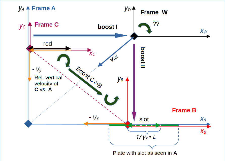
Illustration 2: Can one instead of frame A use an intermediate frame W to achieve another sequence of two boosts (“boost I” and “boost II”) to get from frame C to frame B?
Could we not go the other way round? I.e.: Can we first apply a boost in x-direction from frame C to a frame W, which co-moves with the rod in vertical direction in A and which horizontally co-moves with the slot in A? And afterward apply a simple boost in y-direction from frame W to frame B?
Would such a boost sequence R not give us the very same results?
We can pose the question a bit differently: Does the following relation hold?
(Again, the encircled “+”-sign symbols the operation succession.) It seems that we have good reasons to assume that
So, the question is :
Meaning:
Is the succession of two simple boosts along two perpendicular axes commutative?
In case you followed this series, you will certainly not answer too quickly:
Illustrations like the one above seduce us to interpret changes between observer perspectives in a Newtonian way. But the relativistic reality is more complicated. W moves diagonally in A – and we posed already questions regarding the choice of a suitable coordinate system in posts XII and XIII. In addition, moving objects (as the slot in frame C) may experience a Thomas-Wigner rotation. We saw this e.g. for the rod when we changed the observer perspective from frame A to frame B.
The physical and the mathematical answers to the problem of commutativity
If the Theory of Special Relativity makes sense at all, then the physical answer to the question above must be: The results derived by both approaches must be physically equivalent. Independent of the question in which target frame the succession of boosts ends. So, the transformed vector components must have the same physical consequences for the development of a selected scenario in the target frames of the different boost sequences.
Mathematically, however, a subtle question lurks in the background:
Does a simple boost along the y-axis of the first boost’s target coordinate system in W (with an xW-axis aligned with the one of C and the rod) really lead us to frame B attached to the slot? Would a Thomas-Wigner rotation of the the slot (and at the same time of the coordinate system of B with an x-axis along the slot), not require some correction of a resulting inclination angle?
One thing seems to be clear and is consistent with previous psosts: “Boost sequence S” leads us to a natural description of the observations in B in a coordinate system that has a xB–axis aligned with the slot.
Questions regarding boost sequence R
Our question posed above can actually be separated: 1) What do the orientations and motions of the rod and slot in W look like after “boost I” ? 2) In which coordinate system of W does an assumed “boost II” in “vertical direction” make sense at all?
From our efforts regarding W (see posts XII to XVI) we know the answers already.
First, let me remind you that we, of course, found a diagonal motion of the slot vs. the rod from the perspective of frame C (attached to the rod). See the next image taken from post VI:
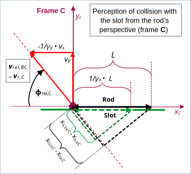
Illustration 5: The slot’s diagonal movement in the collision scenario as seen from a frame C attached to the rod.
Based on previous exercises, a short consideration shows that a LT to the right along the xC-axis will inevitably lead to a Thomas-Wigner rotation of the diagonally moving slot. We have derived respective angles already in previous posts (see e.g. post XVII). I leave details of such basic considerations to the reader. Below, I will just use the results which we have already derived for a perception of the collision scenario in W.
Boost I leads us to a coordinate system in W with an xW-axis aligned with the rod
A boost along an xC-axis (aligned with the rod) logically leads to a coordinate system of W with an x-axis aligned with the rod there, too.
In post XVII we have already collected all information about data that an observer in W would register for the collision scenario. The following drawing presents the most important aspects.
The difference in comparison to the corresponding illustration (3) in post XVII is the result of a simple rotation of the coordinate system to align the xW-axis with the rod. I have called the respective x-axis of this particular coordinate system the xr,W-axis.
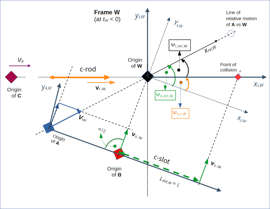
Illustration 4: Inclination of the rod vs. the slot of the collision scenario in frame W.
If we performed a “boost II” along the axis yr,W, then we might catch up with the slot in its vertical movement. We just have to chose a proper relative velocity in yr,W-direction. However, the slot’s velocity component in the perpendicular horizontal direction would not vanish during a LT. The slot would inevitably move diagonally in any target frame moving along the yr,W-axis.
A direct boost II in a coordinate system of W with axes xr,W and yr,W would NOT end up in a frame attached to the slot – in contrast to what happens in the “boost sequence S”. We would end up in a frame co-moving horizontally with the rod and see an inclination of the slot with its x-axis. In addition, the slot would move in this target frame.
Consequences – and a remedy for the boost sequence R
Our findings first of all answer the main question of this post:
A direct sequence of two boosts along non-collinear axes is in general not commutative.
Therefore, our idea presented in illustration 3 is an illusion: We cannot just boost to W, directly continue afterward with a “boost II” along the yr,W-axis in W and expect that we arrive in a frame attached to the slot as in “boost sequence S“. Furthermore, the slot experiences a Thomas-Wigner rotation during the LT between our frames C and W.
But, we know already that the direction of the slot’s velocity vector is vertical to the orientation of the slot. So, along this line of the slot’s motion, we could apply a simple boost if we wanted to get to the slot’s frame B. However, there is an angle between the rod’s and the slot’s orientations. Therefore, such an approach would require an additional rotation in W ahead of boost II.
I.e., we can remedy this problem by inserting a rotational operation between boost I and boost II:
- Use a “boost I” to get from frame C to frame W and to a coordinate system CSR,W having an xr,W-axis aligned with the rod.
- Compensate for the inclination angle between the rod and the slot in W: Apply a spatial rotation transformation of all data to a coordinate system CSS,W with an xs,W-axis oriented in parallel to the slot.
- Apply a boost along the ys,W-axis of CSS,W to get data in the target frame B.
This is true in general:
Compensating the non-commutativity of boost sequences along non-collinear axes requires a spatial rotation. This is a hint pointing to deeper symmetry properties of the mathematical group of Lorentz Transformations. These symmetry properties have not only consequences for building fundamental theories in theoretical physics. They also have direct consequences for for e.g. the transformation of angular momentum data in special relativity.
Conclusion
In this post we have used previous results of this series to analyze a sequential combination of so called boosts along different non-collinear axes. We have found that a combination of such operations is non-commutative. The difference is due to inclination angles caused by the Thomas-Wigner rotation. One can compensate for this difference by adding a spatial rotation transformation to one of the sequences.
In the next concluding post I will give an outlook on other related problems a reader could study.