This post series is a about a paradox based on the length contraction effect in the Special Theory of Relativity [STR]. In the first post of this series I have described a special setup and two reference frames for the so called “rod/slot paradox“. See the link below. In the present post I first will summarize some important initial settings for the posed scenario. Afterward we will apply the Lorentz transformation and derive that the rod’s diagonal movement towards the slot comes with a constant inclination angle between the rod and the x-axis measured by observers in the frame in which the slot is at rest.
Previous post:
Scenario setup
The graphics below shows (x,y)-coordinate systems of two reference frames – frame A and frame B. The rod is falling vertically in frame B, while the slot resides at rest in frame A. Relative to frame B, frame A moves horizontally with a negative constant velocity –νx. There is no vertical relative motion between the frames. In frame B a long thin rod is oriented in parallel to the xB-axis. It moves vertically downwards from a height yB = h to the level yB = 0 in frame B. In frame A we have a plate with a slot in it – also oriented along the x-axis and at level yA = 0. The plate and the slot do not move in frame A. Extensions of objects vertical to the (x,y)-coordinate planes of the frames are irrelevant. The slot is infinitesimally bigger than the rod in x- and z-direction.
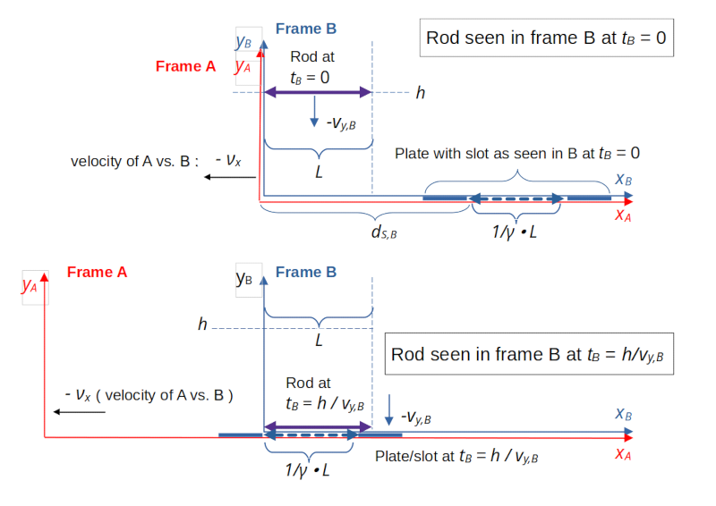
Illustration 1: Reference frames B and A, the rod and the plate with the slot
Our thin, but lengthy rod has a proper length L. The slot in the plate also has proper length L; we ignore the infinitesimal excess in x-direction in forthcoming calculations.
Remember that the proper length of an object is measured with the object being at rest in some frame. No forces and no accelerations are at work in our scenario. Seen from the slot, the rod approaches diagonally with two constant orthogonal components of its velocity. I use subscripts A and B below to indicate where certain coordinates and quantities are measured.
- In frame B the rod rests with respect to its horizontal position. But the rod falls vertically there with a constant velocity vrod = -vy,B.
- In frame A the plate (and thus also the slot) are at rest (at vertical position yA = 0). I.e., relative to frame B, frame A moves to the left with a horizontal velocity –νx.
- At time tB = tA = 0 the origins of the coordinate systems of the reference frames A and B coincide.
- At time tB = 0 the rod is located at height yB = h in frame B. The rod will reach the vertical position of the slot (yB = 0) at a time tB = tg,B.
- The slot is placed in frame A such that the slot’s left end reaches the rod’s left end after a time period ΔtB = tg,B has passed in frame B.
- In frame A the rod moves diagonally, but with constant horizontal velocity νx towards the slot.
Basic events in our scenario are defined with respect to frame B. For a further analysis we need to determine respective coordinates in frame A.
A predetermined crash of the rod at the slot’s right border
From illustration 1 you can derive a predetermined development in our scenario: In frame B the conditions are defined such that the rod has no chance to pass the slot vertically without an accident and touching the plate. Why is this?
In B the rod falls vertically with constant velocity vrod = – vy,B = const.
It is oriented in parallel to the x-axes of the frames. So, in B, both the right and the left end of the rod will reach the plate and the slot at the same time tg,B = h / vy,B:
The measurement process for a length is defined such that the length of an object should be measured by observers measuring the spatial coordinates of the object’s ends at the same time. In B we can measure the positions of the rod’s ends or the slot’s ends e.g. at tB = tg,B.
We know from a basic course in special relativity [SR] that the length contraction effect will give us a diminished slot length in B (compared to what observers would measure in frame A):
(c is the velocity of light). I.e.:
Hence, at tB = tg,B in B the rod’s length L will be to big for the slot. We therefore expect the rod to crash at our plate at a an x-coordinate (measured in B)
The paradox seems to be that length contraction in frame A will shorten the slot by a factor \( 1 / \gamma \lt 1\). Therefore in A one is tempted to assume that the rod falls through the slot there. We will see in the next post that this assumption is false.
What we will learn in this post is the following: In frame A the right end of the rod actually touches the plate at a later time than the left end of the rod. Thus we actually can not apply the length contraction formula in A to get the spatial distance between these two events. Could this insight help us to resolve the paradox? Well, we will see …
Lorentz transformation and the transformation of velocities
For the given setup of our frames A and B let us write down the required formulas of the Lorentz transformation [LT] of event coordinates between our two frames:
The “+” and “-” signs result from our movement of frame A against B in negative x-direction. An important point in our forthcoming analysis will be based on the transformation of velocity components:
You may wonder why the velocity component in y-direction experiences a modification, whereas the spatial coordinates in y-direction remain unchanged. The reason is the time dilation effect between observers at fixed positions in A versus observers at fixed positions in B. We shall look at this in detail in a minute.
Note that the denominator in the velocity formulas is important in our scenario as a pure vertical movement e.g. in a frame B will lead to a diagonal one in frame A – with a horizontal velocity component vx,A = νx.
Note that an unchanged y-coordinate does NOT mean that two events in B measured at the same time tB with the same y-coordinate yB, but different x-coordinates will be transformed to reach the same y-coordinate in A at a common identical point in time tA in A.
The rod falls in frame A with a lower vertical velocity than in frame B
Let us first see what the vertical velocity component of the rod in frame A looks like. From the LT formulas we get:
This is consistent with the fact that due to time dilation any time difference measured in a frame B, which moves with relative to a frame A, appears stretched in frame A. So, when e.g. the rod falls from yB = h down to yB = 0 in a time interval ΔtB = tg,B, the respective time interval in frame A will be measured to be longer, ΔtA = γ • tg,B :
So, any of the rod’s end points will cover the vertical distance yA = h in frame A with a properly reduced vertical velocity exactly in the prolonged time interval there:
This means that event coordinates of the rod’s movement measured in A and B are, indeed and of course, mapped by the LT in full consistency with the time dilation effect.
Initial key events occurring in B at tB = 0
Let us now look at some initial events in B. I.e., we turn to analyzing initial events triggered by the vertical movement of the rod in frame B at tB = 0.
We pick the events Event 1 (E1) and Event 2 (E2) which we have defined in the first post. These events occur when the ends of the rod pass the line yB = h in frame B. The respective coordinates are given by:
The subscripts “r,l,B” and “r,r,B” mark the left and the right ends of the rod in B, respectively. We indicate to which event “Ex” the coordinates belong by “|Ex“. The right subscripts at the brackets for the event coordinates (e.g. [x, y, t]B ) mark the frame of reference.
We have distinguished event E1 for the left end of the rod from event E2 for the right end of the rod because these events may transform differently. Due to our scenario’s specific setup (horizontal orientation of the rod in B) these two events for the two ends of the rod do happen at the same time tB = 0 in frame B.
Let us use the Lorentz transformation to find the coordinates of these events in frame A. We again mark coordinates belonging to event “Ex” by “|Ex” and use the subscripts “r,l,A” and “r,r,A” for the coordinates of left and right ends of the rod, this time in A:
This means:
That was easy! Let us try to understand these results a bit better …
The rod’s ends do not pass the starting height h at the same time in frame A
We assume that the rod has been falling with vy,B already for a while before it passes the line yB = h in frame B at tB = 0. Then the first strange consequence of the above results is :
But as the rod is moving with velocity νx relative to frame A in our scenario: Should we not expect a length contraction?
This is an important point, which deserves some discussion. Any length measurement process is defined such that we perform measurements at different spatial positions, but at the very same point in time in a chosen frame of reference (here at tA in A). The time value must be taken, of course, from synchronized clocks at the positions in question. So, length measurements in x-direction use coordinates of two events with different xA-coordinates, but with one and the same time coordinate tA.
However, our events E1 and E2, which occur at the same time tB = 0 in frame B, transform into two separate events occurring at different times in frame A!
Remember a basic consequence of the STR: What happens at the same time in one frame, does not necessarily happen at the same time in another frame. This is exactly what we find here:
While the left and the right sides of the rod pass y=h at the same time tB = 0 in B, we find in frame A
- A: The rod’s left edge passes the geometrical point (xA, yA) = (0, h)A at tA = 0 .
- A: The rod’s right end passes (γ • L, h)A at a later point in time tA = γ • νx /c2 • L > 0 .
So, determining the length difference between these events is not a measurement of the length of the rod in A.
Consistency Check: What would happen if we measured the length of the rod at tA = 0, instead? We can use the Lorentz transformation again to get the corresponding point in time for the rod’s right end in frame B:
This tells us that instead of picking E2 ∼ [L, h, 0]B, we would have to look at an earlier event in B:
E2R ∼ [ L, hR, -νx / c2 • L ] in B. At an earlier time in B the rod in B has not yet reached yB = h. Thus we have to take yB = hR, instead of h. We now transform this particular event E2R to get the following coordinates in A:
As we can directly conclude from the xA-coordinate: This would indeed have given us a length contraction!
Shifts in space and in time
The Lorentz transformation tells us that observers in A watch event E2 at coordinates with different values in comparison to what observers in B measure. In particular the time coordinate changed.
However, to understand things better we should also look at events which happen at the same time in A. We have seen that such events are E1 and E2R. Respective distances in the spatial coordinates of the rod’s end points are:
Consistency check: Note that between tA|E1 = 0 and tA|E2 = γ • νx / c2 • L the right end of the rod indeed and consistently to E2 moves in A to the following xA position
What do our derived shifts in space coordinates for the right end point of the rod mean geometrically?
In frame A the rod moves with a constant inclination angle Ψ relative to the x-axis and thus also relative to the slot
Any point on the rod to the right of its left end xr,l,A (tA=0) crosses the horizontal line given by yA = h later then tA = 0. And with distance the time difference grows linearly. This means that observers in frame A register a rod which not only is falling diagonally, but which is also rotated against the xA-axis:
Frame A: The rod shows a constant inclination angle Ψ with a horizontal line through its left end point.
I have depicted the situation as seen in frame A schematically in the next illustration. The rod as seen in A is drawn in red color. The blue rod representation refers to the situation in B and is just included for comparison reasons.
Note: Scaling and angles are not realistic.
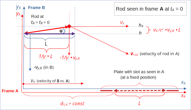
Illustration 2: The rod at tA = tB = 0 – seen from frame A
From the perspective of A we deal with an object (the rod) moving diagonally. The rod’s horizontal velocity in A is given by the relative velocity νx of frame B in A. In the co-moving frame B the object is oriented along the x-axis. In A, however, the rod’s its orientation exhibits by a positive and constant inclination angle with the x-axis and parallel horizontal lines.
The inclination angle Ψ of the rod with the x-axis is given by
The angle’s sign obviously depends on the signs of the components of the object’s velocity components in frame A:
A falling object moving in positive x-direction in A would show a negative inclination angle. A falling object moving in negative x-direction in A would show a negative inclination angle. But an object moving in positive y-direction and in negative x-direction would show a positive inclination again.
Side remark: Our result is, by the way, related to the so called aberration effect in the STR. When you replace vy,B with c (for a vertically propagating light wave front in B coming from a star above), and vx by its negative (star is moving towards an observer located to the left) then you get a negative angle. Any telescope would have to be orientd vertically towards the wave front. One can show with the help of our formulas that the inclination angle for the telescope is given by tan(π/2 – |Ψ|) = cot (|Ψ|) ≈ 1/β (neglecting the deviation of γ from 1.0). This is indeed the correct result.
Due to the squared velocity of light in the denominator Ψ is a relative small angle. The angle Φ the velocity vector vrod has in A versus the x-axis (!) is negative in our case and given by :
The absolute value of this angle Φ is typically much bigger than Ψ.
The attentive reader has of course noticed that the so called time shift or time phase seen in a moving frame A for events which happen at the very same time tB in B was of major importance for our derivation:
This time shift or time phase is obviously proportional to the distance of events in B from e.g. the origin of B. This corresponds to the statement that synchronized clocks along the x-direction in B appear out of synchronization in frame A. The distance dependency is a bit hard to swallow. In addition, depending on the sign of the relative velocity between the frames in question the shift effect can go in both directions. I will use this a forthcoming post to build a scenario in which the rod actually moves through the slot without touching the plate.
But, enough for today …
Conclusion
In this post we have looked at two reference frames
- a frame B with a thin and lengthy rod oriented in parallel to the x-axis and falling vertically downwards,
- a frame A moving horizontally away from frame B in negative direction with a constant relative velocity –νx and with a slot located a level yA = 0 and a fixed x-position.
The coordinate systems of frames A and B had the same orientation. We have studied some first consequences of the Lorentz transformation for the description of the rod’s movement from the perspective of frame A. A major result was that observers in A describe the movement of the rod not only as a diagonal movement, but that the rod is oriented in A such that it exhibits a small inclination angle with the x-axis and the slot there.
We have also seen that events happening at the same point in time in B have a time difference in frame A. The transformation results indicated in addition that the right end of the rod may touch the plate later and at a larger distance to the right of the slot’s left end in A than expected. In the next post I will look closer at this distance and discuss a consequence – namely that in our scenario the rod will not pass the slot unharmed – neither in frame B, nor in frame A. Stay tuned …